


9
CAUTION
T
O PREVENT IMPROPER AND DANGEROUS OPERATION DUE TO WIRING ERRORS,
LABEL ALL WIRES PRIOR TO DISCONNECTION WHEN SERVICING CONTROLS.
V
ERIFY PROPER OPERATION AFTER SERVICING.
For unit protection, use a time delay fuse or HACR circuit
breaker that is in excess of the circuit ampacity, but less than
or equal to the maximum overcurrent protection device. DO
NOT EXCEED THE MAXIMUM OVERCURRENT DEVICE SIZE
SHOWN ON UNIT DATA PLATE.
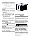
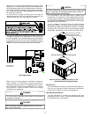
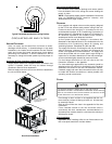
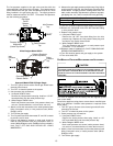
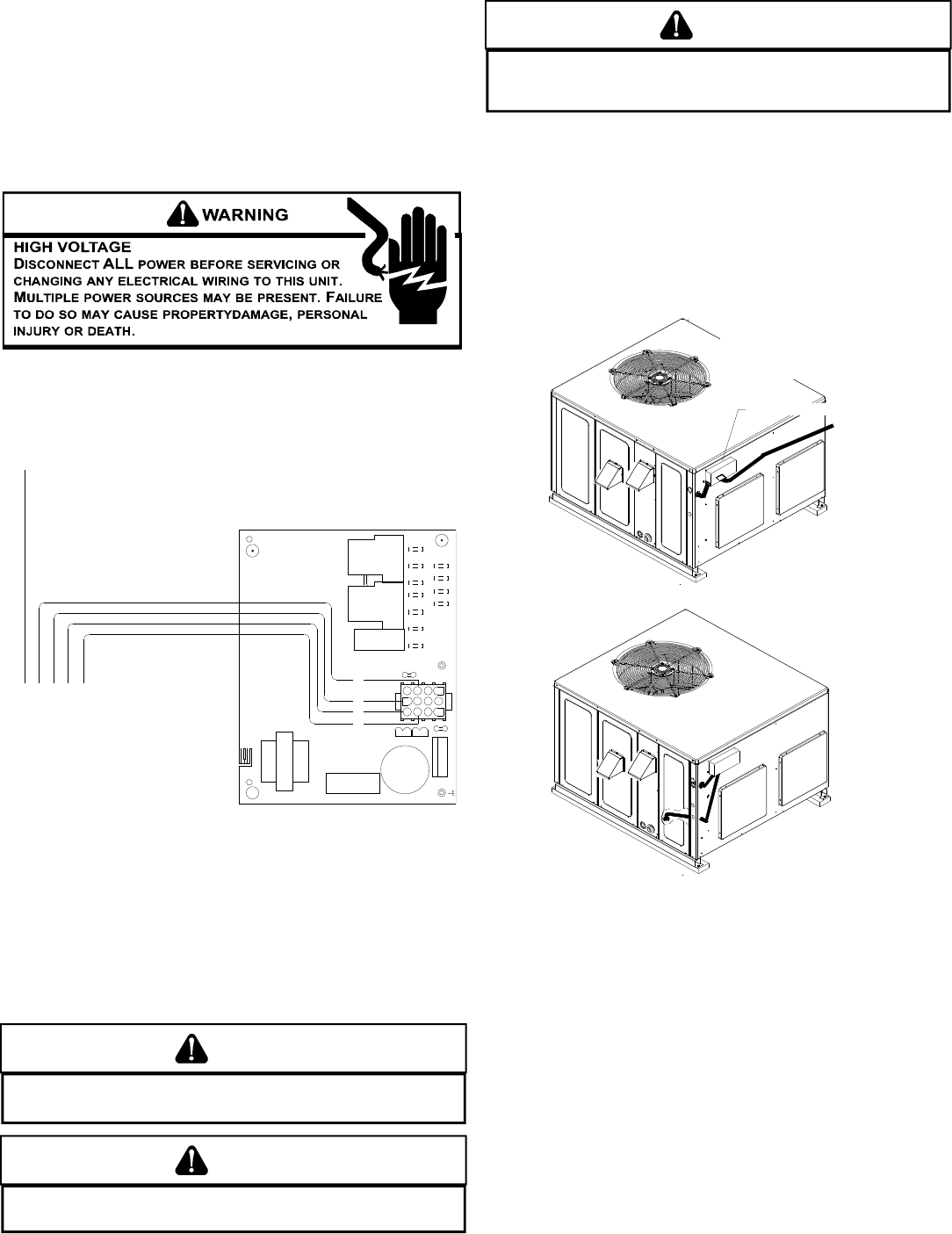
All line voltage connections must be made through
weatherproof fittings. All exterior power supply and ground
wiring must be in approved weatherproof conduit. Low voltage
wiring from the unit control panel to the thermostat requires
coded cable. See below for ground level and rooftop wiring.
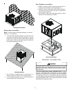
Electrical Power Directly To Junction Box
Electrical Power Routed Through Bottom of Unit
Note:Junction box location
shown is optional and is
for illustration purposes only.
JUNCTION BOX
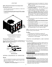
Typical Electrical Wiring Unit Voltage
UNIT V OLTAGE
The unit transformer is factory connected for 230V operation.
If the unit is to operate on 208V, reconnect the transformer
primary lead as shown on the unit wiring diagram.
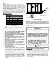
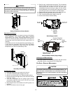
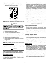
HEAT ANTICIPATOR S ETTING
The heat anticipator is to be set by measuring the load
(amperage) at the “R” circuit. Follow the instructions provided
by the thermostat for more details.
Movement of air must not be obstructed by furniture, door,
draperies, etc. The thermostat must not be mounted where it
will be affected by drafts, hot or cold water pipes or air ducts in
walls, radiant heat from fireplace, lamps, the sun, television,
etc. Consult the Instruction Sheet packaged with thermostat
for mounting instructions.
All units have one stage of heating and one stage of
mechanical cooling. Units which will have economizers may
use thermostats with one or two stages of cooling.
The units are designed for operation on 60 hertz current and
at voltages as shown on the rating plate. All internal wiring in
the unit is complete. It is necessary to bring in the power supply
to the contactor as shown on the unit wiring diagram which is
supplied with each unit. 24 volt wiring must be connected
between the unit control panel and the room thermostat.
C
3
2
1
6
5
9
8
11
12
Y
R
4
7
10
G
W
G
WYR
2
T1
C22
P2
P3
FUSE 3 AMP MAX
P1
12
1
7
4
4
5
3
3
6
9
FS
6
10
7
F1
11
8
11
10
12
9
K1
12
T2
BREAK FOR TWO STAGE
COMPRESSOR
24VAC 50 /60Hz 400mA MAX.
L1DI
K2
L1 HEATUNUSED
K4
K3
COOL
1068-83-400A
MODE L
1068-400
B18099-18
ANSI Z21.20 AUTOMATIC IGNITION SYSTEM
L2L2L2L2
ECON
120
135
150
SPEED-UP
LOW VOLTAGE
CONNECTOR
Low Voltage Wiring
Refer to the unit wiring diagram for electrical connections.
When installed, the unit must be electrically grounded in
accordance with local codes or in the absence of local codes,
with the National Electrical Code, ANSI/NFPA No. 70, and/or
the CSA C22.1 Electrical Code. Ensure low voltage
connections are waterproof.
WARNING
T
O AVOID THE RISK OF ELECTRICAL SHOCK, WIRING TO THE UNIT MUST BE
POLARIZED AND GROUNDED.
CAUTION
T
O AVOID PROPERTY DAMAGE OR PERSONAL INJURY DUE TO FIRE, USE
ONLY COPPER CONDUCTORS.