


17
CABINET F INISH M AINTENANCE
Use a fine grade automotive wax on the cabinet finish to
maintain the finish’s original high luster. This is especially
important in installations with extended periods of direct
sunlight.
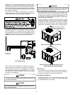
CLEAN OUTSIDE COIL (QUALIFIED SERVICER ONLY)
The coil with the outside air flowing over it should be inspected
annually and cleaned as frequently as necessary to keep the
finned areas free of lint, hair and debris.
CONDENSER, EVAPORATOR, AND INDUCED DRAFT MOTORS
Bearings on the air circulating blower motor, condenser motor
and the combustion fan motor are permanently lubricated.
No additional oiling is required.
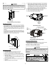
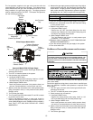
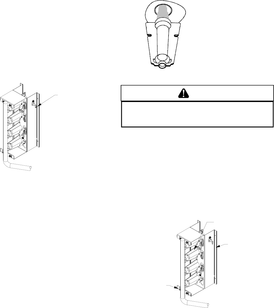
FLAME SENSOR (QUALIFIED SERVICER ONLY)
A drop in the flame current can be caused by a nearly invisible
coating on the flame sensor. This coating, created by the fuel
or combustion air supply, can be removed by carefully
cleaning the flame sensor with steel wool.
NOTE: After cleaning, the microamp signal should be stable and
in the range of 4 - 6 microamps DC.
Flame
Sensor
Flame Sensor
FLUE PASSAGES (QUALIFIED SERVICER ONLY)
At the start of each heating season, inspect and, if necessary,
clean the unit flue passage.
CLEANING FLUE PASSAGES (QUALIFIED SERVICER ONLY)
1. Shut off electric power and gas supply to the unit.
2. Remove burner assembly by disconnecting the gas line
and removing the manifold bracket from the partition
panel.
3. Remove the flue from the induced draft blower and the
collector box cover from the partition panel.
4. The primary heat exchanger tubes can be cleaned using
a round wire brush attached to a length of high grade
stainless steel cable, such as drain cleanout cable. Attach
a variable speed reversible drill to the other end of the
spring cable. Slowly rotate the cable with the drill and
insert it into one of the primary heat exchanger tubes.
While reversing the drill, work the cable in and out several
times to obtain sufficient cleaning. Use a large cable for
the large tube, and then repeat the operation with a small
cable for the smaller tube. Repeat for each tube.
5. When all heat exchanger tubes have been cleaned, replace
the parts in the reverse order in which they were removed.
6. To reduce the chances of repeated fouling of the heat
exchanger, perform the steps listed in “Startup,
Adjustments, and Checks”.
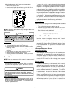
MAIN BURNER FLAME (QUALIFIED SERVICER ONLY)
Flames should be stable, soft and blue (dust may cause
orange tips but must not be yellow). The flames must extend
directly outward from the burner without curling, floating or
lifting off.
Check the burner flames for:
1. Good adjustment
2. Stable, soft and blue
3. Not curling, floating, or lifting off.
Burner Flame
WARNING
T
O AVOID PERSONAL INJURY OR DEATH DUE TO ELECTRIC SHOCK,
DO NOT REMOVE ANY INTERNAL COMPARTMENT COVERS OR ATTEMPT ANY
ADJUSTMENT.
C
ONTACT A QUALIFIED SERVICER AT ONCE IF AN ABNORMAL
FLAME SHOULD DEVELOP.
At least once a year, prior to or during the heating season,
make a visual check of the burner flames.
NOTE: This will involve removing and reinstalling the heat exchanger
door on the unit, which is held by two screws. If you are uncertain
about your ability to do this, contact a qualified servicer.
If a strong wind is blowing, it may alter the airflow pattern within the
unit enough that an inspection of the burner flames is not pos-
sible.
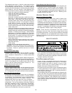
CLEANING BURNERS
1. Shut off electric power and gas supply to the unit.
2. Remove the screws securing the manifold to the burner
retention bracket. Remove the manifold and rotate each
burner counterclockwise to remove.
Burner
Bracket
Burner
Manifold
Manifold Assembly
3. Remove the burners.
4. Use a bottle brush to clean burner insert and inside of the
burners.