


13
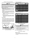
8. Measure the gas supply pressure with burners firing. Adjust
supply pressure using the Inlet Gas Supply Pressure table
shown below. If supply pressure reading differs from the
table, make necessary adjustments to pressure regulator,
gas piping size, etc., and/or consult with local gas utility.
Propane Gas
Natural Gas
Inlet Gas Supply Pressure
Minimum:5.0" W.C. Maximum :10.0" W.C.
Minimum:11.0" W.C. Maximum :13.0" W.C.
9.Turn OFF all electrical power and gas supply to the system.
10.Remove the manometer hose from the hose barb fitting
or inlet pressure boss.
11.Replace inlet pressure tap:
a. Honeywell VR8215 valve:
Remove the 1/8” NPT hose barb fitting from the inlet
pressure tap. Replace the inlet pressure boss plug and
seal with a high quality thread sealer.
b. White-Rodgers 36G22 valve:
Turn inlet pressure test screw in to seal pressure port
(clockwise, 7 in-lb minimum).
12.Retest for leaks. If bubbles form, SHUT DOWN GAS AND
REPAIR LEAKS IMMEDIATELY.
13.Turn ON electrical power and gas supply to the system.
14.Turn valve switch ON.
GAS MANIFOLD PRESSURE MEASUREMENT AND ADJUSTMENT
T
O
PREVENT
UNRELIABLE
OPERATION
OR
EQUIPMENT
DAMAGE
,
THE
I
NLET
GAS
SUPPLY
PRESSURE
MUST
BE
AS
SPECIFIED
ON
THE
UNIT
RATING
PLATE
WITH
ALL
OTHER
HOUSEHOLD
GAS
FIRED
APPLIANCES
OPERATING
.
CAUTION
This valve is shipped from the factory with the regulator preset
(see control label).
Consult the appliance rating plate to ensure burner manifold pres-
sure is as specified. If another outlet pressure is required, follow
these steps.
1. Turn OFF gas to furnace at the manual gas shutoff valve
external to the furnace.
2. Turn OFF all electrical power to the system.
3. Outlet pressure tap connections:
a. Honeywell VR8215 valve:
Remove the outlet pressure boss plug. Install an 1/8”
NPT hose barb fitting into the outlet pressure tap.
b. White-Rodgers 36G22 valve:
Back outlet pressure test screw (outlet pressure boss)
out one turn (counterclockwise, not more than one turn).
4. Attach a hose and manometer to the outlet pressure barb
fitting (Honeywell valve) or outlet pressure boss (White-
Rodgers valve).
5. Turn ON the gas supply.
The line pressure supplied to the gas valve must be within the
range specified in the chart on the next page. The supply pressure
can be measured at the gas valve inlet pressure tap or at a hose
fitting installed in the gas piping drip leg. The supply pressure
must be measured with the unit OFF. To measure inlet pressure,
use the following procedure.
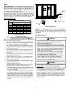
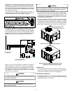
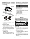
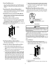
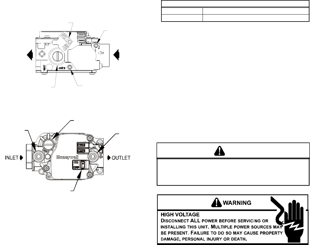
Pressure Regulator
Adjustment
(Under Cap Screw)
Gas Valve
On/Off
Selector
Switch
INLET
OUTLET
Inlet Pressure
Tap
Outlet Pressure
Tap
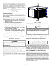
White-Rodgers Model 36G22
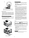
Gas Valve On/Off
Selector Switch
Inlet
Pressure
Tap
Pressure Regulator
(under cap screw)
Outlet
Pressure
Tap
Honeywell Model VR8215 (Single-Stage)
1. Turn OFF gas to furnace at the manual gas shutoff valve
external to the furnace.
2. Turn OFF all electrical power to the system.
3. Inlet pressure tap connections:
a. Honeywell VR8215 Valve:
Remove the inlet pressure boss plug. Install an 1/8” NPT
hose barb fitting into the outlet pressure tap.
b. White-Rodgers 36G22 valve:
Back inlet pressure test screw (inlet pressure boss) out
one turn (counterclockwise, not more than one turn).
4. Attach a hose and manometer to the outlet pressure barb
fitting (Honeywell valve) or inlet pressure boss (White-
Rodgers valve).
5. Turn ON the gas supply.
6. Turn On power and close thermostat “R” and “W” contacts
to provide a call for heat.
7. Using a leak detection solution or soap suds, check for
leaks at outlet pressure boss plug (Honeywell valve) or
screw (White-Rodgers valve). Bubbles forming indicate a
leak. SHUT OFF GAS AND REPAIR ALL LEAKS
IMMEDIATELY!