


9
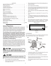
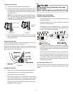
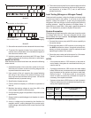
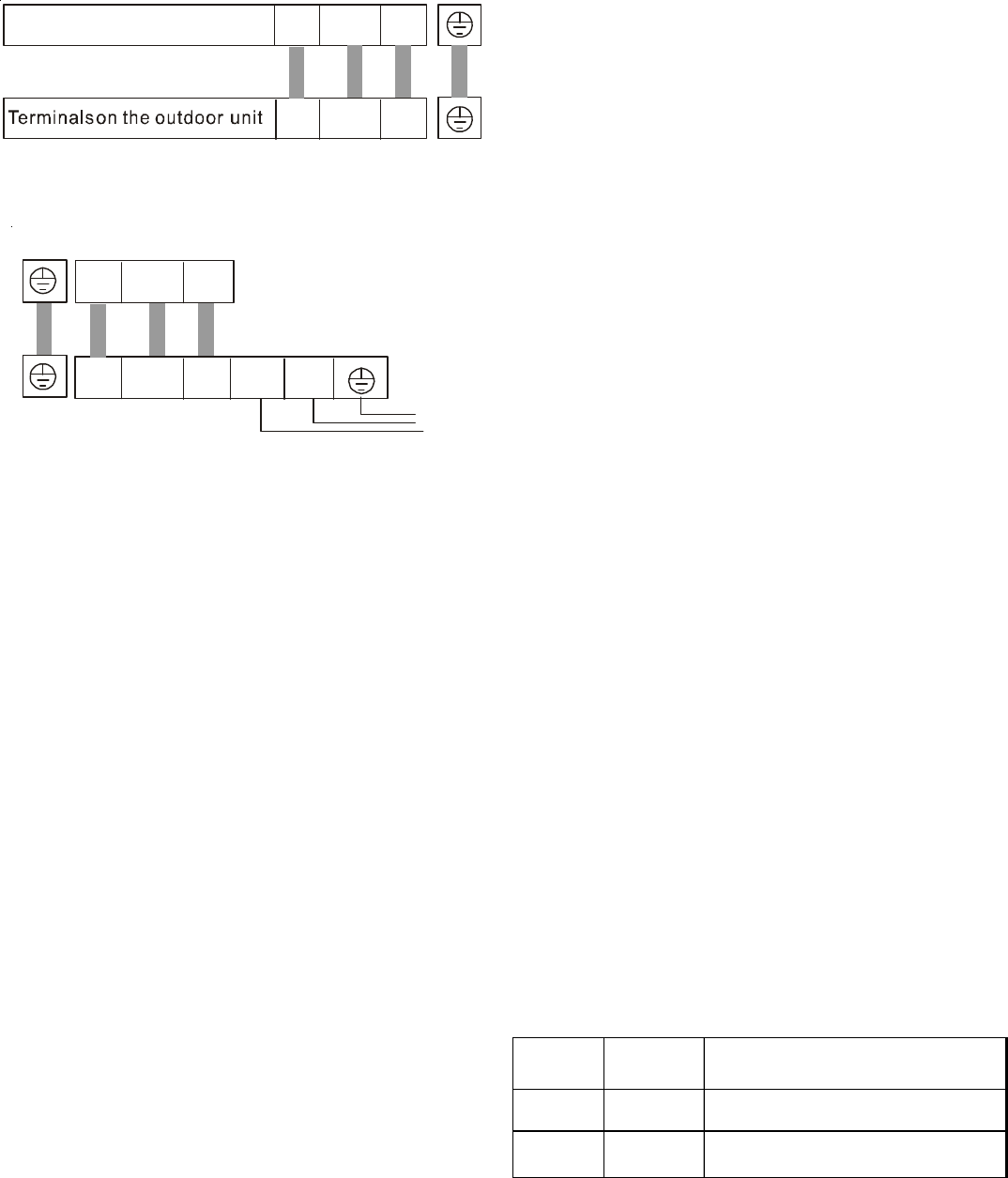
Terminals on the indoor unit
L N S
L N S
Model A
Terminals on the indoor uni
t
L N S
Te r mi na ls o n
the outdoor unit
1(L) 2(N) S L N
Power
supply
Model B
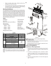
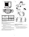
3. Secure the wire onto the control board with the cord clamp.
4. To prevent the ingress of water, form a loop of the con-
nective wires as illustrated in the installation diagram of
the indoor and outdoor units.
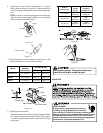
5. Insulate unused cords (conductors) with PVC-tape. Route
them so they do not touch any electrical or metal parts.
IMPORTANT NOTES:
After the above conditions have been met, ensure the following
notes are met:
1. A dedicated power circuit must be in place for the unit.
Wire the unit as shown in the circuit wiring diagram that
is posted inside the control cover.
2. Upon receipt of the unit, examine the screws fastening
the wiring in the casing of the electrical fittings, since
they may have become loose during transit. All must be
fastened securely to prevent arcing.
3. Specification of power source.
4. Confirm electrical capacity is sufficient for operation of
the unit.
5. Maintain the starting voltage at more than 90% of the
rated voltage marked on the name plate.
6. Confirm the wire gauge is as specified in the power source
specification.
7. Always install an earth leakage circuit breaker in a wet or
moist area.
8. A drop in voltage may be caused by the vibration of a
magnetic switch, causing damage to the contact point,
fuse breakage, disturbance of the normal function of the
overload.
9. The means to disconnect from a power supply should be
incorporated in the fixed wiring and have an air gap con-
tact separation of at least 1/8” (3 mm) in each active
(phase) conductor.
Leak Testing (Nitrogen or Nitrogen-Traced)
Pressure test the system, using dry nitrogen and soapy water
to locate any leaks in the system. If you wish to use a leak
detector, charge the system to 10 psi using the appropriate
refrigerant, then use nitrogen to finish charging the system to
working pressure. Apply the detector to suspect areas. If
leaks are found, repair them. After repair, repeat the pressure
test. If no leaks exist, proceed to System Evacuation.
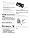
System Evacuation
Condensing unit liquid and suction valves are closed to contain
the charge within the unit. The unit is shipped with the valve
stems closed and caps installed. Do not open valves until
the system is evacuated.
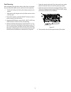
1. Connect the vacuum pump with 250 micron capability to
the service valves.
2. Evacuate the system to 250 microns or less using suc-
tion AND liquid service valves. Using both valves is nec-
essary as some compressor create a mechanical seal
separating the sides of the system.
3. Close the pump valve and hold vacuum for 10 minutes.
Typically, pressure will rise during this period.
NOTES:
• If the pressure rises to 1000 microns or less and re-
mains steady, the system is considered leak-free; pro-
ceed to start-up.
• If pressure rises above 1000 microns but hold steady
below 2000 microns, moisture and/or non-condensables
may be present or the system may have a small leak.
Return to step 2. If the same result is encountered,
check for leaks as previously indicated and repair as
necessary, then repeat evacuation.
• If pressure rises above 2000 microns, a leak is present.
Check for leaks as previous indicated and repair as nec-
essary then repeat evacuation.
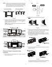
Connective
Pipe Length
Evacuation
Method
Additional Amount of Refrigerant
to be Charged
Less than
16' (5m)
Use
Vacuum Pump
---
More than
16' (5m)
Use
Vacuum Pump
R410A (Pipe Length-5) x 0.3 oz./ft. (20 g/m)
Pipe Length and Refrigerant Amount