


6
1
H
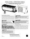
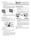
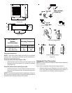
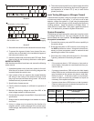
Figure 14A
2
W
1
W
2
Figure 14B
MS* 9 & MS*12
Outdoor
Unit Dimensions
Inches/mm (L1xHxW1) L2 (mm) W2 (mm)
30" x 23" x 11"
760 x 590 x 285
21"
530
11 1/2"
290
Mounting Dimensions
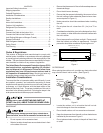
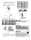
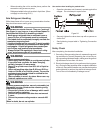
Drain joint installation
NOTE: Drain joints differ slightly according to the different
outdoor units. Inspect your unit and use the installation in-
structions for your specific unit.
For drain joints with seals (Figure 15A):
• Slide the seal onto the drain joint and insert into the
base pan hole of the outdoor unit. Rotate 90° to secure
(see Figure 16).
For drain joints without seals (Figure 15B):
• Insert the drain joint into the base pan hole of the out-
door unit until it remains fixed, accompanied by a click-
ing sound.
NOTE: For protection against water condensation off the out-
door unit during heating mode, connect the drain joint with an
extension drain hose (provided by the installer)
(Figure 15A) (Figure 15B)
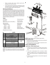
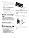
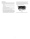
Correct alignment
Incorrect alignment
Figure 16
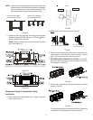
Refrigerant Pipe Connection
NOTE: The main cause of refrigerant leaks is due to defective
flare connections.
Make flare connections using the following procedure:
1. Remove the flare nuts attached to the indoor and out-
door units. Before flaring, slide them over the tubing. It
is not possible to put them on after flaring tubes.