


8
IMPORTANT NOTES:
• If there are safety issues concerning the power supply,
the unit should not be connected until safety issues are
resolved.
• Ensure that the electrical power supply is sufficient to
safely power and run the unit.
• Power voltage should range for 90% - 110% of the rated
voltage.
• Main power switch and surge protector should be 1.5
times the capacity of the maximum current of the unit
and should be installed in the power circuit.
• The unit is to be grounded per NEC.
• Connect all wiring as shown in the Electrical Wiring Dia-
gram located on the panel of the outdoor unit.
• All wiring must comply with local and national electrical
codes. Installation should be done by qualified electri-
cians.
To avoid the risk of personal injury, wiring to
the unit must be properly polarized and
grounded.
• This unit should have a individual branch circuit.
NOTE: The wire gauge and the current rating of the fuse or
breaker are determined by the minimum circuit ampacity and
maximum overcurrent protection device that is indicated on
the nameplate, located on the side panel of the unit. Refer to
the nameplate before selecting the wire, fuse and/or breaker.
Connect the Cable to the Indoor Unit
NOTE: Before performing any electrical work, turn off the main
power to the system.
HIGH VOLTAGE!
Disconnect ALL power before servicing.
Multiple power sources may be present.
Failure to do so may cause property damage,
personal injury or death.
1. The inside and outside connecting wire can be connected
without removing the front grille.
2. Connecting wire between the indoor unit and outdoor unit
should be approved, polychloroprine sheathed, flexible
cord, type designation H07RN-F or heavier.
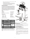
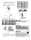
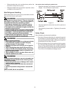
3. Lift up the indoor unit panel, remove the electrical box
cover by loosening the screw as show in Figure 22.
Electrical box
cove
r
Figure 22
4. Ensure the color of the wires of the outdoor unit and the
terminal numbers are the same as the indoor unit’s.
5. Wrap the wires not connected with terminals with insula-
tion tape, so they will not touch any electrical compo-
nents. Secure the wires onto the control board with the
cord clamp.
Connect the Cable to the Outdoor Unit
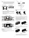
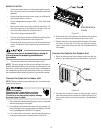
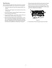
1. Remove the electrical control board cover from the out-
door unit by loosening the screw as shown in Figure 23.
Figure 23
2. Connect the connective wires to the terminals, making
sure the numbers on the indoor unit match with the num-
bers on the outdoor unit’s terminal block. (See Models A
and B.)