


4
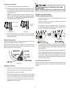
NOTE: Install the mounting bracket and drill the holes in the
wall according to the wall structure and the correspond-
ing mounting points on the mounting bracket. (The
mounting brackets vary according to the model.)
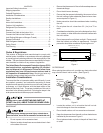
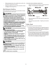
Incorrect orientation
of Installation Plate
Correct orientation
of Installation Plate
Figure 4
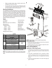
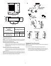
4. Determine the hole positions according to the diagram
detailed in Figures 5A & 5B. Drill one (1) 2.5” hole (
65mm),
slanting slightly to the outside.
NOTE: Always use wall hole conduit when drilling metal
grid, metal plate, etc.
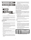
Model B (A: 31” (790mm), B:10” (265mm), C:4” (100mm), D: 6” (151mm)
C
D
Figure 5A
7” (187mm)
6” (150mm)
Figure 5B
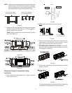
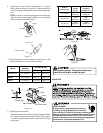
Refrigerant Piping & Condensate Piping
Installation:
5. Drain hose should be installed with a slight downward
slope. (See Figure 6.)
Wall
Indoor
Outdoor
5-7mm
3/16” -1/4”
Figure 6
Do NOT install drain hose as shown in Figure 7.
Do not block water flow by a rise.
Do not put the end of
drain hose into water.
Figure 7
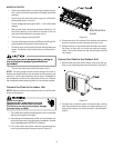
6. When connecting extension drain hose, insulate the con-
necting part of the extension drain hose with a shield
pipe. Do not allow the drain hose to be slack.
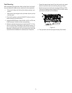
7. REFRIGERANT PIPING INSTALLATION:: For the left-
hand and right-hand piping, remove the pipe cover from
the side panel. (Figure 8.)
Figure 8
8. For the rear right-hand and rear left-hand piping, install as
shown in Figure 9.
Figure 9
To make refrigerant tube connections, refer to Tightening
Connection in the Refrigerant Piping Connection.