


CAUTION
WARNING
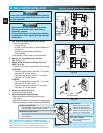
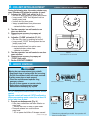
Wall console
Wall button
OR
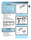
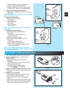
Fig. 4-2
#6 x 1”
pan head screws
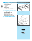
Fig. 4-3
MORE
T
MENT
OPEN
PUSH
LIMITS
TO SET
G4
Y3
B2
W1
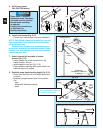
1. Run wire from power head to wall control.
• Place the wall control:
– In sight of door.
– At least 5 feet from floor, so small children can
not reach it.
– Away from moving parts of door and
door hardware.
• Use staples to fasten wire to ceiling and wall.
2. Remove 1/2” insulation from each wire
(Fig. 3-6)(pg. 19).
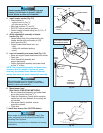
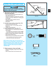
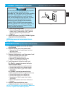
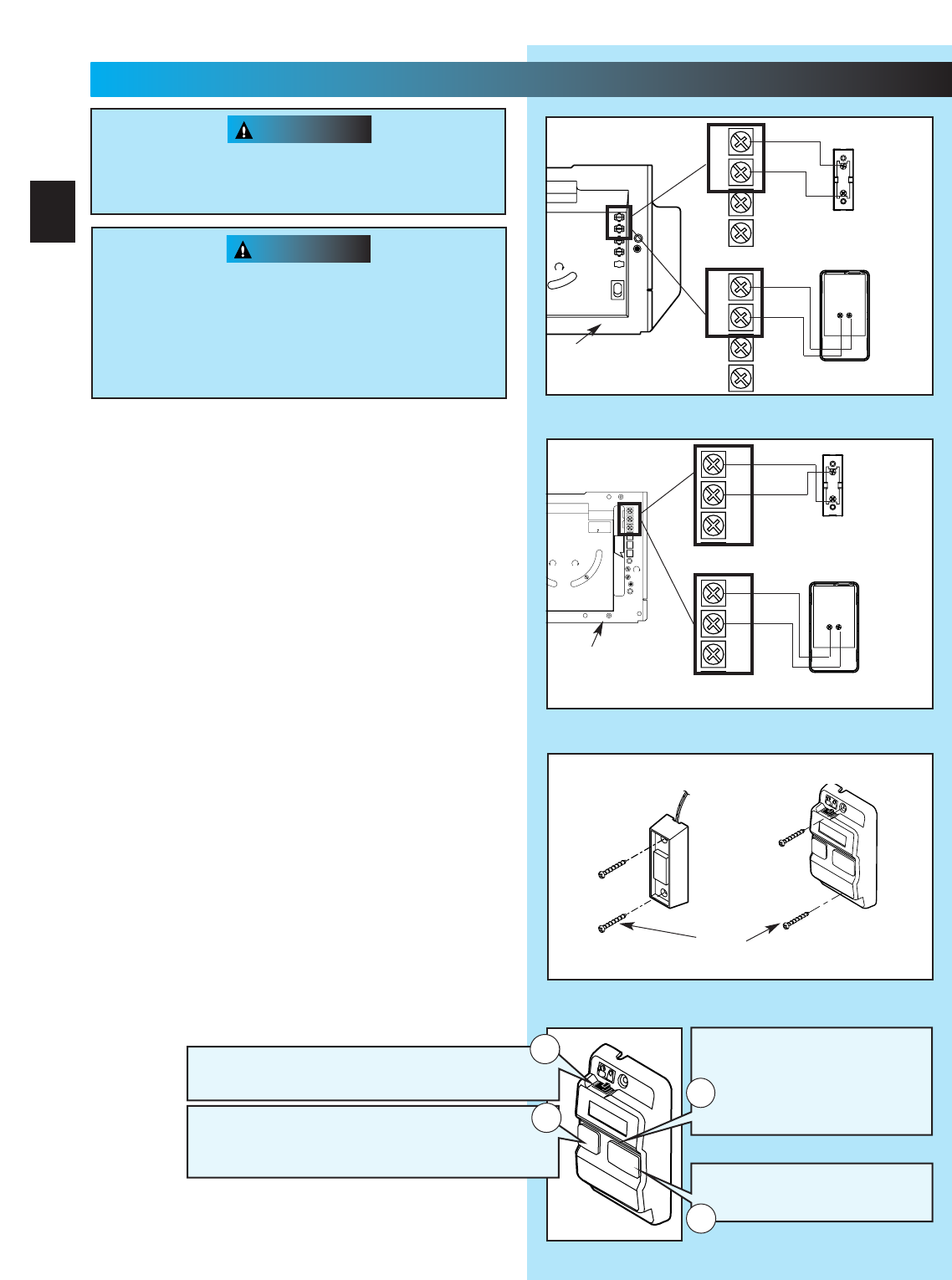
3. Attach wires to terminals (Stealth Fig. 4-1a)
(MAX Fig. 4-1b).
• Loosen, but Do Not remove screw from terminal.
For Stealth.
– Connect striped wires to terminal “2” on power
head and “B” on wall control.
– Connect white wire to terminal “1” on power
head and “W” on wall control.
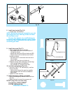
For MAX.
– Connect striped wires to terminal “1” on power
head and “B” on wall control.
– Connect white wire to terminal “2” on power
head and “W” on wall control.
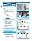
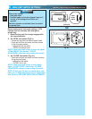
4. Mount wall control (Fig. 4-2).
• Use two pan head screws.
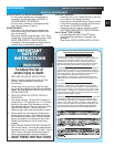
5. Mount entrapment warning label.
• Remove protective backing and stick near
wall control.
• Use tacks or staples to permanently mount Label.
•
Make sure everyone reads and follows WARNINGS.
NOTE: Additional wall controls are available from your
dealer. ONLY ONE OF YOUR WALL CONTROLS MAY BE THE
LIGHTED TYPE. If you have a lighted wall control, all your
additional controls must be un-lighted. More than one
lighted wall control per operator will cause a malfunction.
Power cord must be unplugged before attaching
wires. Be sure wire ends do not touch each other
or other terminals.
• Use of any other wall control will cause the
light not to work and could cause door to
operate by surprise.
• Cut or pinched wires can cause door operator
to malfunction. Drive staples just tight enough
to hold wire.
Fig. 4-1a
1
2
3
4
W
B
BW
White
Striped
Wall
console
terminals
Wall
button
terminals
Power head
terminals
Back view
Back view
1
2
3
4
White
Striped
OR
Power
head
ferminals
Rear view of
power head
Fig. 4-1b
NEC
CLASS 2
1
2
3
4
5
6
MORE
FORCE
PUSH
BUTTON
SAFETY
BEAM
LIMIT
SET
OPEN
FORCE
CLOSE
FORCE
RADIO
SIGNAL
LEARN
CODE
COM
DO NOT
PUSH
LIMIT SET
UNLESS
DOOR IS
ATTACHED
NOTE:
USE ONLY WITH
SERIES II CONTROLS
CLOSE
MORE
OPEN
MORE
OSE OPEN
LIMIT ADJUSTMENT
U.S. Patent No. 5,243,784
5,221,869
CSS
1
2
3
W
B
BW
Striped
White
Wall
console
terminals
Wall
button
terminals
Power head
terminals
power head
terminals
Back view
Back view
Front view of
power head
CSS
1
2
3
Striped
White
EITHER
20
4
...
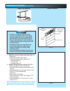
WALL CONTROL INSTALLATION
FOR HELP-1.800.354.3643 OR GENIECOMPANY.COM
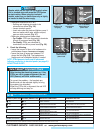
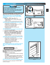
Independent Light Control
–
Controls door operator lights from inside garage
–
Energy-Saver shut-off turns off light 5 minutes after
door activation
Vacation Locking Switch
– LOCK disables controls after door is completely closed
– UNLOCK allows controls to work normally
Lighted Button
–
Shows system is powered
–
Lights when Security Lock
Switch is in UNLOCK position
–
Goes out when Security Lock
Switch is in LOCK position
Door Control Button
–
Open and closes door from
inside garage
1
4
3
2