


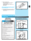
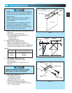
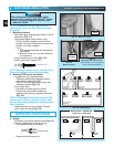
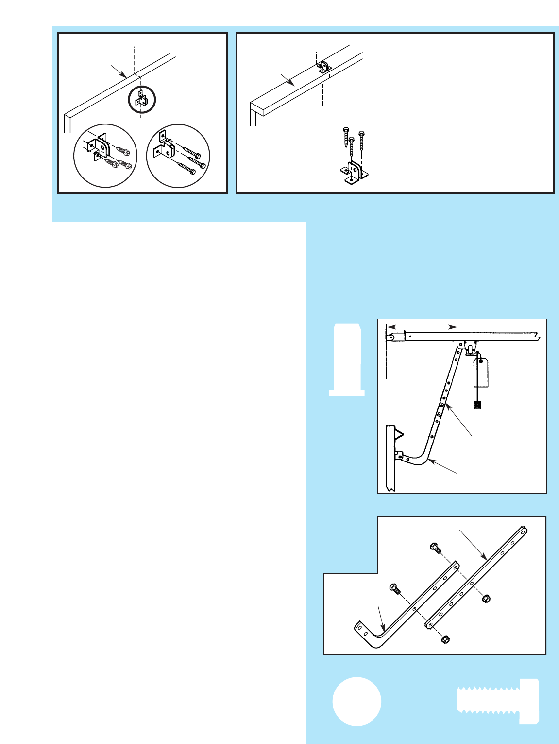
8. Install door bracket (Fig. 2-6).
• Contact door manufacturer.
NOTE: Self-drilling screws are intended for use with
light-weight door only, while lag screws are meant
for wood doors only.
Because door designs vary, modifications may
be required and additional materials needed. Please
contact your door manufacturer with any questions
concerning your door.
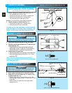
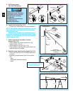
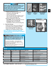
9. Install door arms (Fig. 2-7).
• Attach straight door arm to carriage.
– slip straight door arm into slot at bottom of
carriage as shown.
– secure with clevis pin
[
90
]
and cotter pin
[
89
]
.
• Attach short end of curved door arm to door
bracket as shown.
– slip short end of curved door arm into slot in
door bracket.
– secure with clevis pin and cotter pin.
• Release carriage (See emergency release tag).
– slide carriage towards closed door.
– stop carriage 14” minimum from door.
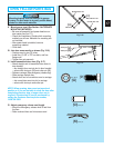
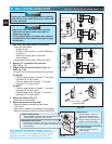
10. Join door arm sections (Fig. 2-8).
• Use two (2) 3/8” x 7/8” hex bolts
[
91
]
, and hex
flange nuts
[
92
]
.
– use any two holes as far apart as possible.
– slide carriage back and forth as needed to
align holes.
• Tighten hex nuts securely.
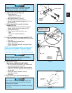
11 . Adjust emergency release cord length.
• Mount the emergency release knob 6 feet from
the floor.
• Retie overhand knot and trim excess cord.
DO NOT plug power cord into outlet.
Go to Section 3-SAFE-T-BEAM
®
SYSTEM INSTALLATION.
– PROCEED TO PAGE 18 –
Fig. 2-8
Straight door arm
Curved door arm
Fig. 2-6
Fig. 2-7
14” MIN.
Straight door arm
Curved door arm
Top of Door
Dessus de la porte
Top of Door
Dessus de la porte
“V”
“V”
“V”