


19
Installation Instructions
VENTING INSTRUCTIONS (cont.)
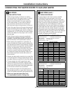
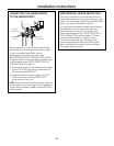
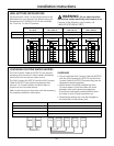
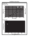
MAXIMUM VENT LENGTH
Maximum System performance is achieved
at a vent length of 21 equivalent feet or less. The
system is capable of 41 equivalent feet vent length
if required, but this reduces system performance.
For vent length calculation, a 90-degree elbow
counts as 6 feet and a 45-degree elbow counts
as 3 feet.
Determine the number of 90-degree elbows in
the vent system. (Two 45-degree elbows count
as one 90-degree elbow.)
Refer to the table to find the maximum vent
length based on the number of elbows.
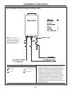
Use the chart below to compute maximum
permissible lengths for venting to outdoors.
NOTE: Factory unit is set to vent up to 21 ft.
for maximum performance. The unit can be
reconfigured to 41 ft. See below or call
1.888.HOTWTER.
VENT LENGTH CALCULATIONS
Total vent length = # straight ft. + # 90-degree
elbow x 6 ft. + # 45-degree elbow x 3 ft.
2
1
CONCENTRIC VENT PIECE EQUIVALENT LENGTH
Straight 1 ft. (per foot length)
90-degree elbow 6 ft. each
45-degree elbow 3 ft. each
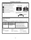
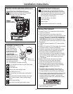
VENTING INSTRUCTIONS
R
efer to the specific instructions on your vent
product for additional installation requirements.
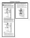
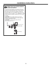
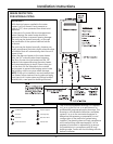
CONDENSATE
Regions of cold climate will create more
condensate in the vent system.
Condensate formation can even occur in
high-efficiency direct vent appliances. To prevent
condensate damage, follow these instructions:
• First remove the black plastic cap, and use 5/8″
ID flexible PVC tubing to drain condensate.
• The condensate trap must contain a minimum
of 3 inches (75 mm) of water. See page 8.
• Dispose of condensate per local codes.
• In applications where condensate could freeze,
such as an unconditional attic space, care should
be taken to prevent condensation line freezing.
Refer to state and local codes for proper disposal
of condensate.
WARNING: If the condensate
collector is not used, the drain pipe must be
capped to prevent exhaust gases and condensate
from entering the building. The cap is supplied on
the appliance.
CAUTION: Without proper drainage
or disposal, condensate will damage the heat
exchanger. Condensate collector on the unit
must be properly connected.
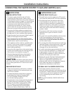
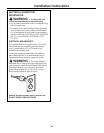
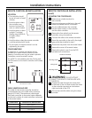
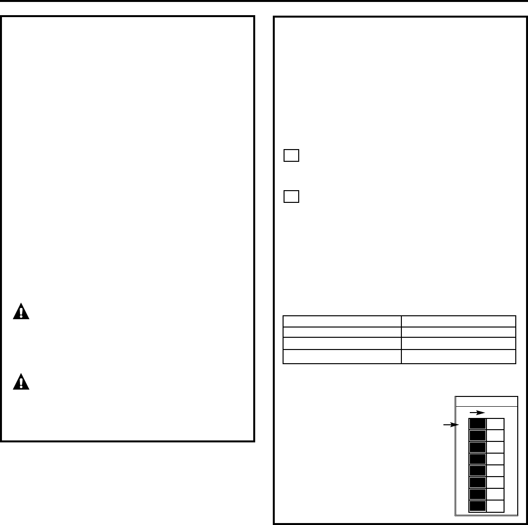
O
F
F
1
2
3
4
5
6
7
8
ON
Switch No.
SW1
*
If the length is greater than
21 ft. (6.4 m), then move dip
switch no. 1 (SW1) to OFF.