


15
Installation Instructions
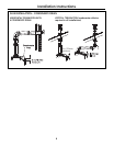
CONNECTING THE WATER HEATER
TO THE WATER SUPPLY
Water connections to the tankless water heater
should follow all state and local plumbing codes.
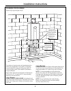
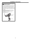
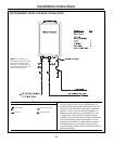
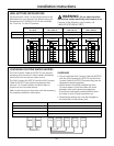
If this is a standard installation, refer to
the diagram on the following page under
RECOMMENDED PIPING FOR BASIC INSTALLATION.
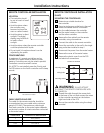
If freeze protection valves are being installed, refer
to the diagram under FREEZE PROTECTION FOR
EXTERNAL PIPING on page 17.
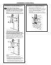
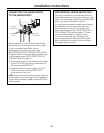
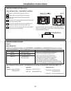
1. Plumb water supply to the tankless water heater
on the 3/4″ MNPT connection at the bottom of
the unit marked WATER INLET.
2. Plumb the home hot water supply to the 3/4″
MNPT connection marked WATER OUTLET
at the bottom of the unit.
NOTE: Make sure water lines to the water heater fit
in the diagram shown on page 9. This is essential if
a pipe cover accessory (model number AGTPCM) is
to be installed.
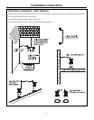
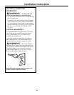
SUPPLEMENTAL FREEZE PROTECTION
I
f the unit is installed in an environment that can
freeze, follow state and local codes and apply heat
trace to ALL water pipe and fittings located outside
(attic, crawl space or building structure).
It is highly recommended in areas where freezing
temperatures occur to install automatic drain
valves that work in the event of a power loss.
Refer to the diagram in the FREEZE PROTECTION
FOR EXTERNAL PIPING section (page 17). These
valves should be wired to a supply current.
In the event of a power loss, the system will
drain automatically. Be sure to test this system
after installation by turning off power to ensure
the system drains properly.
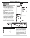
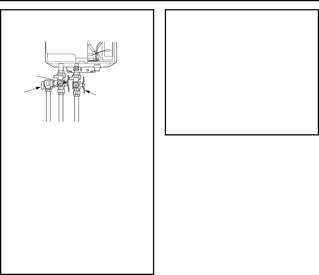
Cold Inlet
Shut Off Valve
Pressure Relief
Valve
Hot Outlet
Shut Off Valve