


12
Installation Instructions
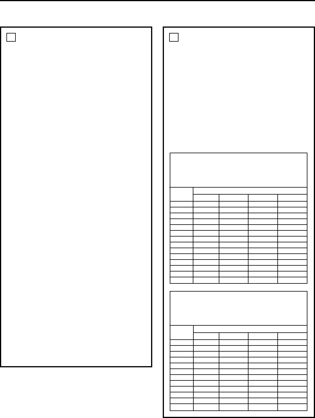
GAS PIPING (cont.)
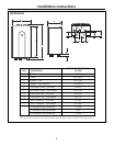
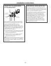
PIPE SIZING PROCEDURE
The gas supply to the home must be capable
of handling the entire gas load of the home,
calculated by adding the BTU rating of each gas
appliance in the home. State and local codes must
be met, as well as utility requirements, to ensure
gas supply to the unit is adequate to meet the
rated demand. Use the charts below as a guide to
size the pipe from the utility meter to the tankless
water heater. Gas line sizing is based on gas type,
the pressure drop in the system, the gas pressure
supplied and the gas line type. Refer to the National
Fuel Gas Code, NFPA 54, and/or your local gas
provider, for proper gas line sizing.
1
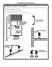
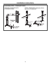
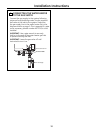
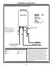
GAS PIPING
GENERAL INSTRUCTIONS
• Make sure gas supply is off prior to making
any connections to the water heater. A manual
gas control valve, provided with this water
heater, must be placed in the gas supply line
to the water heater. A union can be used on
the connection above the shut-off valve for
the future servicing or disconnection of the unit.
• Check the type of gas and the gas inlet pressure
before connecting the water heater. If the water
heater is not of the gas type that the building is
supplied with, DO NOT connect the water heater.
Contact the dealer for the proper unit to match
the gas type.
• Check the gas supply pressure immediately
upstream at a location provided by the gas
company. Supplied gas pressure must be within
the limits shown in the Specifications section.
• Before placing the appliance in operation, all
joints, including the heater, must be checked for
gas tightness by means of leak detector solution,
soap and water or an equivalent nonflammable
solution, as applicable. (Since some leak test
solutions, including soap and water, may cause
corrosion or stress cracking, the piping shall
be rinsed with water after testing, unless it has
been determined that the leak test solution is
noncorrosive.)
• Always use approved connectors to connect the
unit to the gas line. Always purge the gas line of
any debris before connection to the water heater.
• The gas supply line shall be gas tight, sized
and so installed as to provide a supply of gas
sufficient to meet the maximum demand of the
heater and all other gas-consuming appliances
at the location without loss of pressure.
• Any compound used on the threaded joint of
the gas piping shall be a type which resists the
action of liquefied petroleum gas (propane/LPG).
• Refer to an approved pipe sizing chart
if in doubt about the size of the gas line.
1
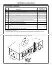
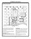
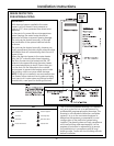
CONNECTING THE WATER HEATER TO GAS AND WATER
PIPE SIZING TABLE – NATURAL GAS
cubic feet per hour Schedule 40 Metallic Pipe
Inlet Pressure: less than 2 psi (55 inches W.C.)
Pressure Drop: 0.3 inches W.C.
Specific Gravity: 0.60
PIPE SIZE (INCHES)
Length 3/4 11
1
/4 1
1
/2
10 273 514 1060 1580
20 188 353 726 1090
30 151 284 583 873
40 129 243 499 747
50 114 215 442 662
60 104 195 400 600
70 95 179 368 552
80 89 167 343 514
90 83 157 322 482
100 79 148 304 455
125 70 131 269 403
150 63 119 244 366
175 58 109 224 336
200 54 102 209 313
PIPE SIZING TABLE – PROPANE GAS
cubic feet per hour Schedule 40 Metallic Pipe
Inlet Pressure: 11.0 inches W.C.
Pressure Drop: 0.5 inches W.C.
Specific Gravity: 1.50
PIPE SIZE (INCHES)
Length 1/2 3/4 11
1
/4
10 291 608 1150 2350
20 200 418 787 1620
30 160 336 632 1300
40 137 287 541 1110
50 122 255 480 985
60 110 231 434 892
80 101 212 400 821
100 94 197 372 763
125 89 185 349 716
150 84 175 330 677
175 74 155 292 600
200 67 140 265 543