


• Support inlet and outlet plumbing in some manner (use
pipe hangers)
to keep the weight off of the valve fittings.
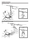
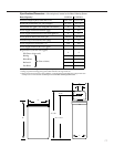
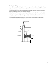
Connect and run the valve drain hose:
• Take a length of garden hose with female fitting and attach
to the valve drain fitting, as shown in Fig. 4.
IMPORTANT:
Make sure the garden hose fitting fits
securely onto the threaded drain port.
• Locate the other end of the hose at a suitable drain point
(floor drain, sump, laundry tub, etc.) that terminates at the
sewer drain.
Check and comply with local codes.
IMPORTANT:
Use a high quality, thick-walled hose that
will not easily kink or collapse. The water softener will
not work if water cannot exit this hose during
regenerations.
• Tie or wire the hose in place at the drain point. High water
pressure will cause it to whip during the back-wash and fast
rinse cycles of regeneration.
Also provide an air gap of at least
1–1/2
″
between the end of the hose and the drain point.
An air
gap prevents possible siphoning of sewer water into the
softener, if the sewer should back-up.
• If raising the drain hose overhead is required to get to the
drain point,
do not raise higher than 8´ above the floor.
Elevating the hose may cause a back-pressure that could
reduce brine draw during regenerations.
4
Step-by-step installation instructions.
• Turn off the gas or electric supply to the water heater, in
the possibility that the water heater may be drained while
draining pipes.
• Turn off the water supply to pipes to be cut and drain the
house water pipes.
• Open both hot and cold faucets.
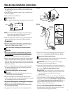
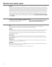
Install bypass valve:
• Remove plastic shipping plug and retainer from valve outlet.
NOTE:
Be sure the turbine and support are firmly in place,
in the valve outlet. Blow into the valve port and
observe the turbine for free rotation.
• Push the bypass valve (lubricate o-ring seals with silicone
grease) into both ports of the valve as shown in Fig. 3.
IMPORTANT:
• Snap the 2 large plastic clips in place, as shown in Fig. 3.
Be sure they snap into place. Pull on the bypass valve to
make sure it is held securely in place.
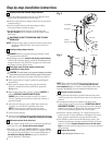
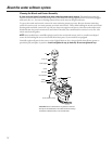
Move the softener assembly into installation position:
CAUTION:
• Secure the resin tank to a stable structure to prevent it
from falling over.
• Locate the brine tank directly next to the resin tank.
• Be sure the installation surface is level and smooth. Sharp
objects under the brine tank may puncture it. If needed,
place the brine tank on a section of 3/4″ thick (minimum)
plywood. Then, place shims under the plywood as needed
to level the softener.
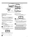
• Connect the black brine valve tube from the brinewell to
the venturi assembly on the valve, using the plastic nut
provided as shown in Fig. 5.
Plumb IN and OUT pipes to and from softener:
CAUTION:
Observe all of the following cautions as you
connect inlet and outlet plumbing.
• Be sure incoming hard water supply is directed to the
softener valve inlet port. If house water flow is from the left,
use a plumbing cross-over as shown in Fig. 1.
•
Do all sweat soldering before
connecting pipes to the bypass
valve.
Torch heat will damage plastic parts.
•
When turning threaded pipe fittings onto plastic fittings,
use care not to cross-thread.
• Use pipe joint compound on all external pipe threads.
3
2
1
Fig. 3
Clips
Turbine
Valve outlet
Turbine support and shaft
7
Fig. 4
O-rings
Drain
fitting
on valve
(Male
garden
hose
fitting)
Valve drain
hose (female
garden hose
fitting)
FLOOR DRAIN
Tie or wire hose
in place
1
1
⁄2″air gap
STANDPIPE
SUMP
LAUNDRY TUB