


6
Consumer Support Troubleshooting Tips Care and Cleaning Operating Instructions Safety Instructions
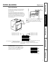
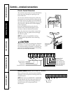
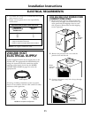
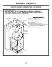
Controls—terminal connections.
Controls–Terminal Connections
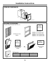
The terminal connections are located behind the
front case panel through an opening on the
front of the unit.
To access the terminal connections, remove the
front panel by removing the filter, taking out the
four front screws, the upper two screws from the
top of the panel and the shipping screws on each
side, if present. (Discard the two side shipping
screws, if present).
Insert the building hook-up wires into the
bottom of the terminals and tighten screws
securely to make the desired connections.
Route the wires from the terminal connections
through the unit wire guides and out through
the case wire guide.
NOTE: The owner is responsible for setting
the appropriate dip switches and connecting
terminals.
CAUTION:
Improper CDC wiring may damage the Zoneline
electronics or cause erratic Zoneline operation.
No common busing is permitted. A separate wire
pair must be run from each separate controlling
switch to each individual Zoneline.
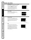
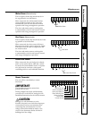
Room Air Sensor (Requires room air sensor kit – RAVRMS)
When connected, the room air sensor will allow
utilization of the temperature limiting and freeze
sentinel features.
NOTE: If GE thermostat RAK147P2 or RAK163P2
is used with the unit, the room sensor kit is not
needed, since temperature limiting and freeze
sentinel features are incorporated in the
thermostats.
Terminal
connections
Route wires
through wire
guides
Room Air Sensor
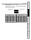
Motion Sensor
Door Sensor
Central Desk Control
Common–Ground
White–Heater
Yellow–Compressor
Black–Reversing Valve
Green–High Speed Fan
Green–Low Speed Fan
Red–24V AC only
Room Air
Sensor