


13
Installation Instructions
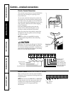
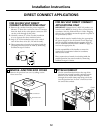
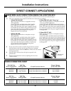
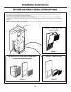
DIRECT CONNECT APPLICATIONS
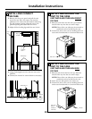
MAKE WIRE LEAD CONNECTIONS INSIDE THE JUNCTION BOX
1. Make all wire connections by using appropriate UL-listed electrical connectors and techniques.
2. Select the applicable wiring situation and follow the instructions accordingly:
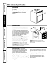
3. Be sure that all wire leads are inside the junction box and not
pinched between the box and the unit. The green insulated
ground wire from the Zoneline MUST be connected to the branch
circuit ground wire.
4. Plug the 9-pin connector into the 9-pin receptacle in the
junction box.
5. Replace the junction box cover by replacing the two screws
removed earlier.
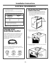
3
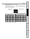
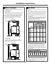
230/208 Volt Wall Plug Heater Wattage
Power Supply Kits Configuration Circuit Protective Device @ 230/208 Volts
RAK3152 Tandem 15 Amp Time-Delay Fuse or Breaker 2.55/2.09 KW
RAK3202 Perpendicular 20 Amp Time-Delay Fuse or Breaker 3.45/2.82 KW
RAK3302 Large Tandem 30 Amp Time-Delay Fuse or Breaker 5.00/4.10 KW
265 Volt Wall Plug Heater Wattage
Power Supply Kits Configuration Circuit Protective Device @ 265 Volts
RAK5157 Does Not Apply 15 Amp Time-Delay Fuse or Breaker 2.55 KW
RAK5207 Does Not Apply 20 Amp Time-Delay Fuse or Breaker 3.45 KW
RAK5307 Does Not Apply 30 Amp Time-Delay Fuse or Breaker 5.00 KW
POWER CONNECTION CHART
Conduit
Make wire lead
connections
• 1-Phase 220-240 VAC
When connecting the Zoneline to a single-phase circuit for
230V applications:
Connect the white and black leads of the Zoneline
power supply kit to the branch circuit L1 and L2
leads. (The white lead of the power supply kit should
be identified by the installer using electrical tape with
some color other than green or white.) Connect the
green lead of the power supply kit to the power
supply and branch circuit ground.
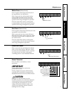
• 3-Phase 208 VAC
When connecting the Zoneline to a three-phase circuit for
208V applications:
Connect the white and black leads of the Zoneline
power supply kit to the branch circuit L1 and L2
leads. (The white lead of the power supply kit should
be identified by the installer using electrical tape with
some color other than green or white.) Connect the
green lead of the power supply kit to the power
supply and branch circuit ground.
• 3-Phase 208 VAC with “Crazy Leg”
When connecting the Zoneline to a three-phase circuit with
“Crazy Leg” for 208V applications:
Connect the white and black leads of the Zoneline
power supply kit to the branch circuit Neutral and L1
leads. (The white lead of the power supply kit should
be connected to neutral.) Connect the green lead of
the power supply kit to the power supply and branch
circuit ground.
• 3-Phase 253-277 VAC
When connecting the Zoneline to a three-phase circuit for
265V applications:
Connect the white and black leads of the Zoneline
power supply kit to the branch circuit Neutral and L1
leads. (The white lead of the power supply kit should
be connected to neutral.) Connect the green lead of
the power supply kit to the power supply and branch
circuit ground.