


Safety Instructions Operating Instructions Care and Cleaning Troubleshooting Tips Customer Service
3
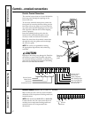
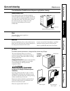
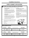
Controls–dip switches. GEAppliances.com
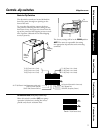
The dip switch controls are located behind the
front case panel, through an opening on the
front of the unit.
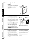
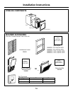
To access the dip switches, remove the front
case panel by removing the filter, taking out the
four front screws, the upper two screws from the
top of the panel and the shipping screws on each
side, if present. (Discard the two side shipping
screws, if present).
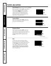
The factory settings will be in the DOWN position.
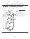
NOTE: The owner is responsible for setting
the appropriate dip switches and connecting
terminals.
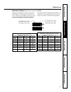
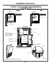
Controls–Dip Switches
Dip
Switches
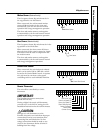
All Electric Heat (Heat pump models only)
When this switch is enabled (UP), heat pump
operation is locked out, causing the unit to
provide only electric resistance heat.
ALL I
2
R (All Electric Heat)
ALL I
2
R (All Electric Heat) (Heat-pump models only)
FREEZ S (Freeze Sentinel)
CONST FAN (Constant ON Fan)
TL1 (H) (Temp. Limit 1–Heat)
TL2 (H) (Temp. Limit 2–Heat)
TL3 (H) (Temp. Limit 3–Heat)
TL1 (C) (Temp. Limit 1–Cool)
TL2 (C) (Temp. Limit 2–Cool)
TL3 (C) (Temp. Limit 3–Cool)
No Function (Reserved for future use)
DUCT (Blower Fan)
OCCUPIED (Occupancy Sensor)
Side
shipping
screw
Side
shipping
screw