


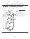
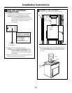
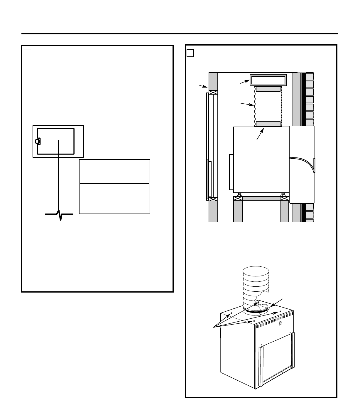
Top duct
Clamp
Case top
duct adjusting
screws
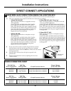
MAKE UNIT ELECTRICAL
CONNECTIONS
1. Connect the thermostat wires to the unit and set
the dip switches to the appropriate settings.
NOTE: See the Controls–Terminal Connections
and Controls–Dip Switches sections of this
manual and the manual with the separate
thermostat for proper connections
and settings.
2. Make power connections to the unit.
NOTE: See the ELECTRICAL REQUIREMENTS and
DIRECT CONNECT APPLICATIONS sections,
as appropriate, of this manual for proper
connections.
3. Replace the case front panel by replacing the four
front screws and the two top screws.
6
Installation Instructions
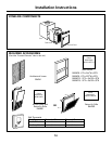
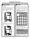
Thermostat
Unit Connections
21
Maximum Wiring
Length for Thermostat
Connection to the Unit
66 ft. for AWG 18
60 ft. for AWG 20
40 ft. for AWG 24
AWG – American Wire Gauge
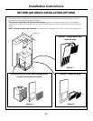
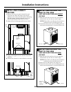
CONNECT THE TOP DUCT
1. Install the duct onto the air discharge outlet.
2. Secure the top duct to the unit by turning the four
case top duct adjusting screws until they are tight.
Use a field supplied clamp to lock the top duct to
the case.
7
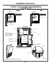
Air
discharge
outlet
Rigid
ductwork
Inside
wall
Flexible or rigid
ductwork