GE Analytical Instruments, Inc. ©2005H Page 14 of 16 DIN 30001 Rev. E
TOC,FLOW SWITCH UPGRADE 2.12CBI
6. Firmware Configuration
It is necessary to configure the binary inputs following the firmware upgrade. Follow these
instructions to configure inputs and select proper polarity.
If more information is required read the Operation and Maintenance Manual concerning
setting up Binary/Digital Inputs. Thoroughly read the chapters on Installation and Operation.
The purpose of the Binary/Digital Input Module is to send a binary/digital signal to the
analyzer that will change operating mode to a PAUSED state.
6.1. Wire the analyzer for binary/digital inputs:
6.1.1. Connect the flow switch to the provided terminal block on the Binary Switch
Module located on the Auxiliary Port, which is on the left side of the analyzer.
6.1.2. Use a continuous closure contact system only. Applying voltage to the Binary
Switch Module may damage the analyzer.
6.1.3. Use either opening in the Binary Switch Module. There is no polarity on the
terminal block.
6.2. Setup the analyzer for binary/digital input:
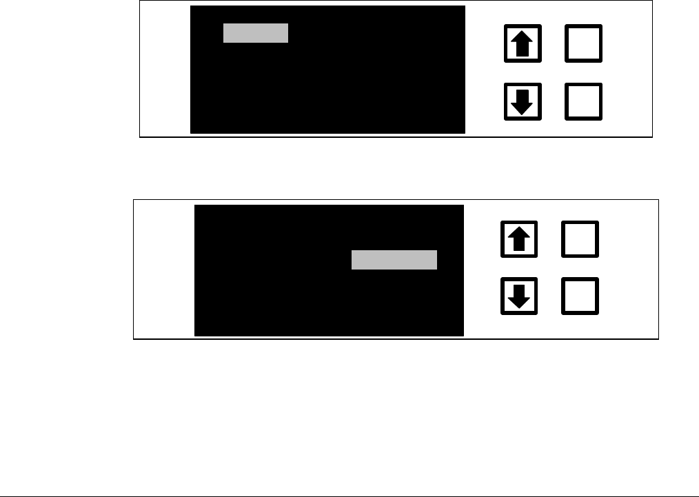
6.2.1. From the MAIN Menu select SETUP using the up/down arrows.
HISTORY
SETUP
ERRORS
CONSUMABLES
CALIBRATE
ENTER
CLEAR
START TOC
FIGURE ELEVEN: Analyzer’s MAIN Menu
6.2.2. Press Enter.
CLOCK
REAGENTS
PRINTER
INPUTS
ENTER
CLEAR
PW
PRESETS
SAMPLE MODE
UV LAMP
OUTPUTS
FIGURE TWELVE: Analyzer’s SETUP Menu
6.2.3. Select INPUTS by using the up/down arrows. Press Enter.


