


9
The flue must be installed in accordance with all local and
national regulation and the current rules in force.
1.FLUE AND CHIMNEY REQUIREMENTS
1.1 The chimney or flue system must comply with the rules in
force, and must be a minimum of 178mm (7î) in diameter.
1.2 The minimum effective height of the flue or chimney must be
3 m (10ft).
1.3 The chimney or flue must be free from any obstruction. Any
damper plates should be removed or secured in the fully open
position, and no restrictor plates should be fitted.
1.4 The chimney should be swept immediately prior to the
installation of the appliance - unless it can be seen to be clean
and unobstructed throughout its entire length.
1.5 Ensure that there is a smooth taper transition from the
fireplace opening into the chimney or flue.
1.6 The flue pull should be checked prior to installation of the
appliance. Apply a smoke pellet to the flue or chimney
opening and ensure that the smoke is drawn into the opening.
If there is not a definite flow, pre-heat the chimney for a few
minutes and re-test the flow.
IF THERE IS STILL NO DEFINITE FLOW, THE CHIMNEY
MAY REQUIRE ATTENTION- SEEK EXPERT ADVICE.
2. INSTALLATION OF THE GAS SUPPLY
2.1 Before installation, ensure that the local distribution
conditions (identification of the type of gas and pressure) and
the adjustment of the appliance are compatible.
2.2 Ensure that the gas supply is capable of delivering the
required amount of gas, and is in accordance with the rules in
force.
2.3 Soft copper tubing and soft soldered joints can be used but
must not be closer than 50mm (2”) to the underside of the
firebox.
2.4 A means of isolating the gas supply to the appliance must be
provided independent of any appliance control.
2.5 All supply gas pipes must be purged of any debris that may
have entered, prior to connection to the appliance.
3. VENTILATION
It is important to ensure that any national ventilation
requirements are taken into account during the installation of
this appliance.
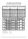
3.1 Ventilation requirements differ according to the model.
Minimum permanent effective free air requirements - if this is
the sole gas appliance in the room - are as follows:
Model No. Description Min. vent cm2
8300UC, P8300UC 16” VFC Radiant
8305UC, P8305UC 18” VFC Radiant 100 See note b.
8310UC, P8310UC 22” VFC Radiant
8301UC, P8301UC RD VFC Radiant NONE
8421UC, P8421UC RD VFC NONE
8463UC, P8463UC Convector See notes a & b
8420UC, P8420UC 16” VFC 15
8461UC, P8461UC Convector
8425UC, P8425UC 18” VFC 20
8466UC, P8466UC Convector
8430UC, P8430UC 22” VFC 30
8471UC, P8471UC Convector See note b
Note a:
Gas input is less than 7kW and flue products clearance under 70
m3/hr. Some countries call for 100cm2 ventilation. Check local
standards.
Note b:
It is essential to check for flue clearance (see diagrams 17/18) If
spillage is detected, it may be necessary to provide additional
ventilation.
3.2 The above table is in addition to any openable window, and
although it must communicate with the outside air, wherever
possible, it can communicate with an adjacent room provided
that the space has a similar vent to the outside.
AIR VENTS MUST NOT BE RESTRICTED.
4. APPLIANCE LOCATION
4.1 This appliance must stand on a non-combustible hearth that is
at least 12mm thick.
4.2 It must be fitted into a non-combustible opening.
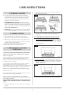
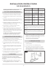
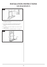
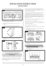
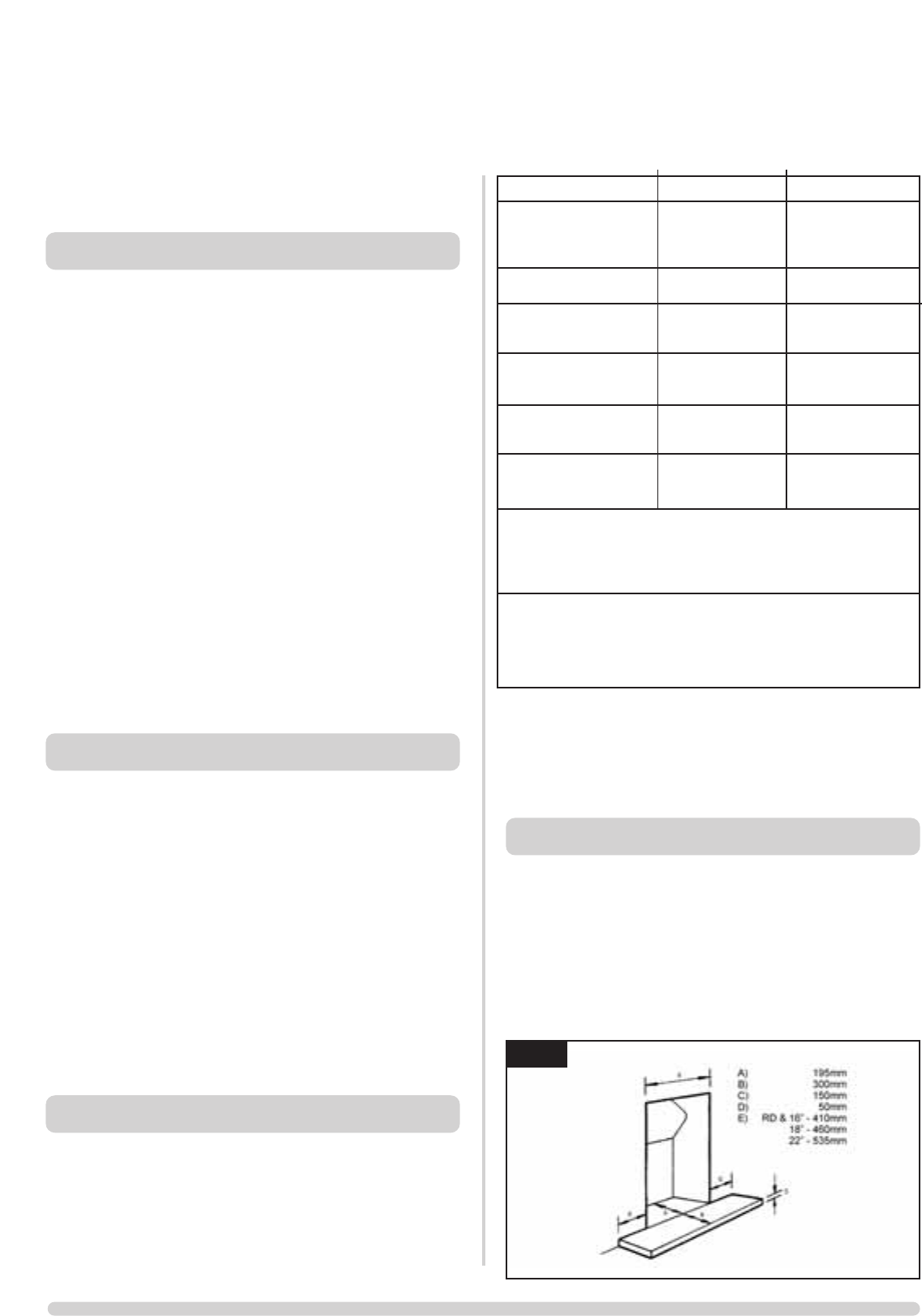
4.3 These appliances must be hearth mounted into a fireplace
opening conforming to National Standards. The minimum
dimensions shall be as shown in diagram 1A for VFC Radiant
fires or diagram 1B for VFC Convector fires. (The shaded area
must be flat and square).
INSTALLATION INSTRUCTIONS
SITE REQUIREMENTS
1A