


12
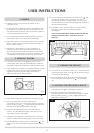
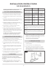
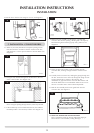
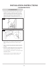
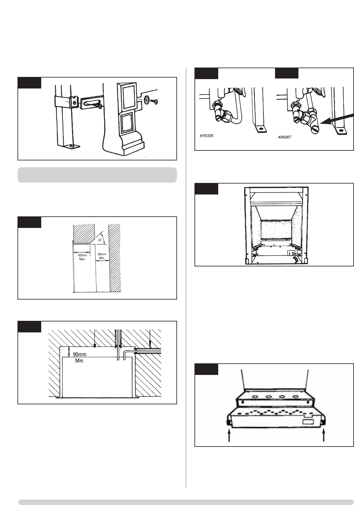
4.8 Fit the fret to the fire front using two screws. See diagram 4.
5. INSTALLATION - CONVECTOR FIRES
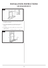
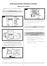
5.1 Make any necessary alterations to fireplace opening. Ensure
that the lintel does not obstruct the flue outlet into the flue,
and that there is a clear space for debris of at least 90mm. See
diagram 5.
5.2 Gas pipe entry must be through one of the holes in the rear
of the convector box. See diagram 6 & 7.
Note: Gas pipes passing through masonry must be protected.
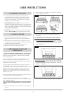
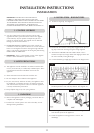
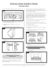
5.3 If the isolation tap is to be fitted under the fire, the GAZCO
GC0060 provides a neat and easy solution. See diagram 7A.
5.4 Remove the fire assembly (see diagram 9), and offer the
convector box into the opening, checking that it fits squarely.
Mark the fixing holes and the gas pipe entry positions. See
diagram 8.
5.5 Fit the gas pipe into position, ready for passing into the
convector box, ensuring enough remains to connect to the
fire.
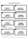
5.6 Carefully fit the convector box, feeding the piping through into
the box. Secure the box to the wall, through the flange or base
ensuring that the box is square in the opening. Any
undulations or gaps between the convector box and the wall
should be filled with a non-combustible material. Do not use
silicone as it makes future removal almost impossible.
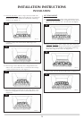
5.7 Refit the fire assembly and front air guide back into the
convector box. See diagram 9.
5.8 HAVE YOU PURGED THE GAS SUPPLY PIPES.
This is essential to expel any foreign matter that might get
blown into the valve assembly causing blockages.
INSTALLATION INSTRUCTIONS
INSTALLATION
4
5
6
7
7A
8
AR0311
AR0300
AR0200
AR0313
AR0314
9