


20
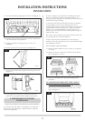
5. ODS PILOT UNIT
Note: The pilot unit on the appliance is a non serviceable unit due
to the complex nature of its manufacture. Replacement of the
complete unit must be carried out when one of the following
items becomes faulty:
Pilot injector
Ignition electrode
Thermocouple
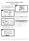
5.1 Carry out operations (a) to (d), section 4.
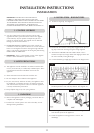
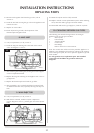
5.2 Gently pull the ignition lead off the electrode. See diagram 5
arrow A.
5.3 Remove the two screws securing the pilot assembly. See
diagram 5 arrow B.
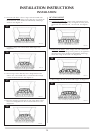
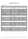
5.4 Undo the thermocouple connection at the back of the gas
valve. See diagram 6 arrow A.
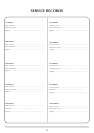
5.5 Replace with a new pilot assembly, set the spark gap. See
diagram 7.
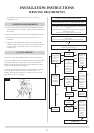
5.6 After reassembly, check for gas soundness and carry out a
flame failure functional check details in the flow chart,
especially the mag drop out time.
6. GAS VALVE
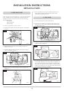
6.1 Turn the gas supply off at the isolation device.
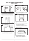
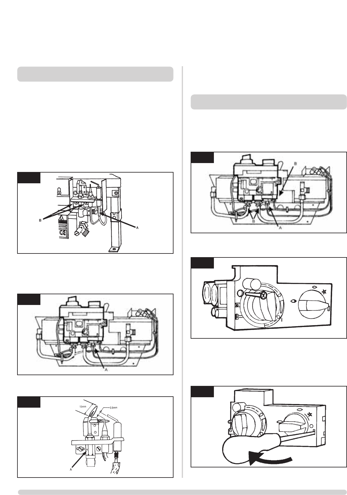
6.2 Disconnect the 2x8mm and 1x4mm gas pipe fittings at the
back of the gas valve and also disconnect the thermocouple,
see diagram 8 arrow B.
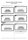
6.3 Undo the single screw that secures the left hand side of the
control cover, see diagram 9.
6.4 To release the right hand side of the control cover insert the
narrow blade screwdriver into the slot shown in diagram 10,
lever it gently and pull from the right hand side at the same
time. The cover will now come off, there is a small cylindrical
metal spacer inside the cover, this must be kept and replaced
on the fixing screw during re-assembly.
INSTALLATION INSTRUCTIONS
REPLACING PARTS
5
8
9
10
6
7
AR0305
AR0945
AR0097
AR0915
AR0916
AR0945