


21
6.5 Disconnect the ignition lead from the gas valve, refer to
section 27.
6.6 Undo the two bolts securing the gas valve to the appliance and
remove the valve.
6.7 Replace in reverse order.
6.8 Check all joints for gas leaks, check operation of the
thermocouple and ignition lead.
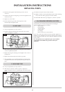
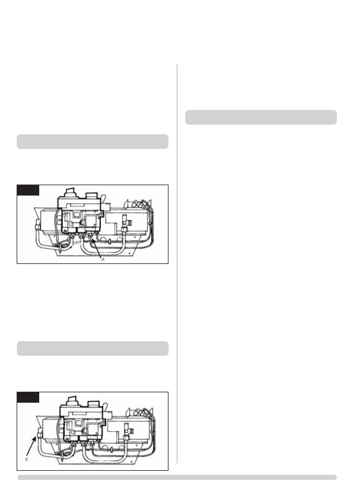
8. MAG UNIT
7.1 Carry out operations (a) to (d), section 4.
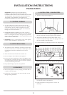
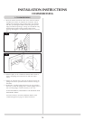
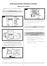
7.2 Undo the mag unit retaining nut at the back of the control
valve. See diagram 11 arrow A.
7.3 After removing the retaining nut, the mag unit can be tapped
out and a replacement fitted.
7.4 Replace the mag unit retaining nut and tighten. Note - this is a
gas-tight seal.
7.5 Replace the thermocouple and check for gas leaks.
7.6 After reassembly, carry out the flame failure functional check
as detailed in the flow chart, especially the mag unit drop out
time.
9. MAIN INJECTOR
8.1 Carry out operations (a) to (d), section 4.
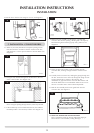
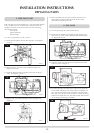
8.2 With the fire removed, undo the injector compression
nut (see diagram 6 arrow C), pull the pipe clear of the injector
body.
8.3 Rotate the injector until it is fully removed.
8.4 Replace with the correct replacement injector. When ordering,
always state the model, gas type and serial number.
8.5 Reassemble and turn the gas supply on, check for any leaks
10. CHANGING BETWEEN GAS TYPES
The following parts must be changed when converting an
appliance from one gas type to another:
• Main injector
• Pilot assembly
• Aeration adjuster
• Control valve
• Data Badge
Refer to Gazco for a Conversion Kit
Note: The control valve will be set for the particular Appliance. In
addition a new databadge will need to be ordered. In all instances,
when ordering new parts, be sure to quote the appliance type and
serial number.
Use only genuine Gazco replacement parts. Non-standard
components will invalidate the guarantee and may be
dangerous.
11
6
INSTALLATION INSTRUCTIONS
REPLACING PARTS
AR0945
AR0945