


11
INSTALLATION INSTRUCTIONS
SITE REQUIREMENTS
1. FLUE AND CHIMNEY REQUIREMENTS
WHEN INSTALLING A FLUE SYSTEM PLEASE REFER TO
THE MANUFACTURER’S INSTRUCTIONS.
and flues by their temperature, pressure and resistance to
corrosion, condensation and fire. To identify the correct flue
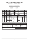
system, the minimum flue specification is shown in the
Technical Specification
by this system.
The flue must be installed in accordance with all local and
national regulations and the current rules in force:
spigot to the roof terminal
metres (10ft)
fully open position and no restrictor plates fitted
installing the appliance, but it need not be swept if you can
see the chimney is clean and free from obstruction
throughout
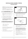
2. FLUE OPTIONS
There are three suitable Conventional Flues:
• Stud work is Top Exit only - Twin Wall Rigid
127mm (5”)
• Top Exit - Builder’s Opening Lined
127mm (5”)
• Rear Exit - Builder’s Opening Unlined
178m (7”) minimum
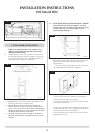
3. GAS SUPPLY
THIS APPLIANCE IS INTENDED FOR USE ON A GAS
INSTALLATION WITH A GOVERNED METER.
3.1 Make sure local distribution conditions (identification of the
appliance are compatible before installation.
and is in accordance with the rules in force.
3.3 You can use soft copper tubing on the installation and soft
3.4 A factory fitted isolation device is part of the inlet
connection; no further isolation device is required.
3.5 All supply gas pipes must be purged of any debris that may
have entered prior to connection to the appliance.
3.6 The gas supply enters through the silicone panel located on
through
3.7 The gas supply must be installed in a way that does not
restrict the removal of the appliance for servicing and
inspection.
4. VENTILATION
IMPORTANT: Ensure any national ventilation
requirements are taken into account during installation
of the fire.
UK ONLY:
does not normally require any additional permanent
ventilation.
The Studio 2 must have permanent ventilation with a
minimum open area of 5.85cm
2
.
FOR THE REPUBLIC OF IRELAND REFER TO THE RULES
IN FORCE FOR VENTILATION REQUIREMENTS
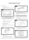
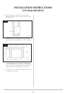
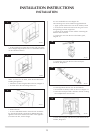
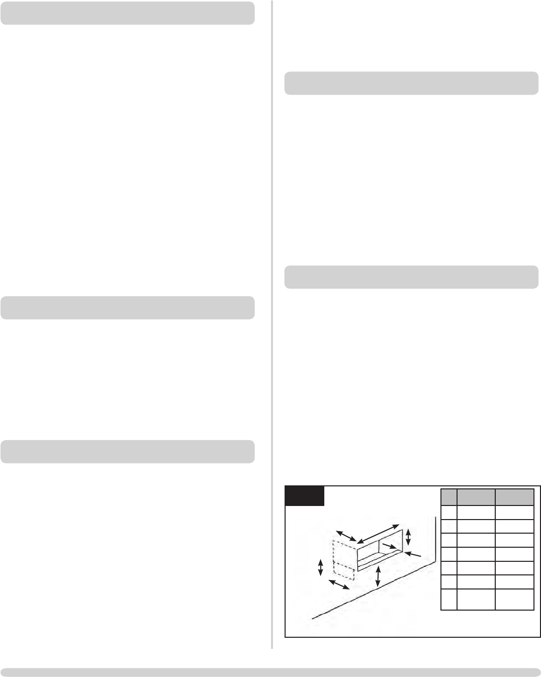
5. APPLIANCE LOCATION
NOTE: It is recommended you construct the back panel
of the fireplace from natural materials cut into three or
more sections to prevent cracking. Resin-based materials
may not be suitable. This appliance is an effective heat
producer and attention must be paid to the construction
and finish of the fireplace.
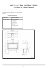
opening, the front of the wall must be cut out down to the
level on which the appliance is to stand. Then, to obtain the
correct dimensions shown in Diagram 1a, the lower section
of wall must be reconstructed as shown in Diagram 1a
5.1 This appliance must stand on a non-combustible base that is
at least 12mm thick; the minimum opening dimensions are
shown in Diagram 1a.
AR1906
1a
C
D
A
E
G
F
B
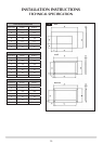
Studio 1 Studio 2
A 760mm 960mm
B 440mm 440mm
C 350mm 350mm
D 85mm 85mm
E 305mm 305mm
F 45mm max 45mm max
G 175mm
min
175mm
min