


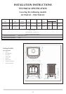

19
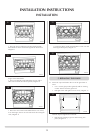
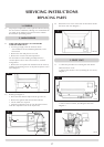
6.2 There is a small cylindrical metal spacer inside the cover,
this must be kept and replaced on the fixing screw during
re-assembly
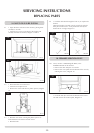
• Disconnect the ignition lead from the gas valve
• Undo the two bolts securing the gas valve to the
appliance and remove the valve, Diagram 9 (C)
• Replace in reverse order
• Check all joints for gas leaks
• Check operation of the thermocouple and ignition lead.
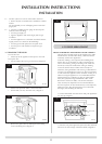
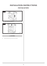
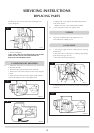
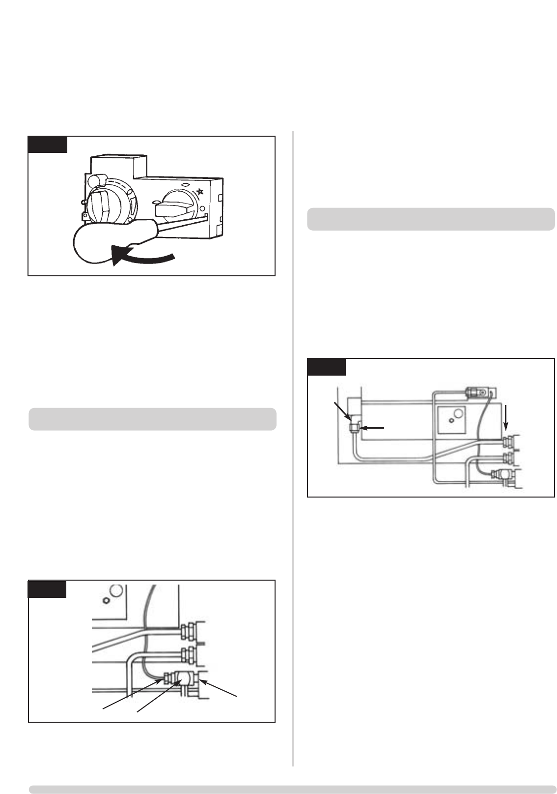
7.1 • Turn the gas supply off at the isolation device, referring
to Diagram 12
• Undo the thermocouple connection from the back of the
gas valve (A)
• Pull the sensor leads clear and remove the interrupter
block (B)
• Undo the magnetic valve-retaining nut from the back of
the control valve (C)
• Gently tap out the magnetic valve and replace with a
new unit
• Replace the retaining nut and tighten, Diagram 12.
12
AR1441a
C
B
A
7. MAGNETIC SAFETY VALVE
11
AR0916
7.2 • Reassemble the interrupter block and leads
• Secure the thermocouple connection in the rear of the
gas control. (Do not overtighten)
• Turn the gas supply on and
• Check the entire pipework and valve joints for any leaks
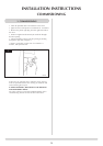
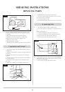
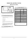
8.1 • Turn the gas supply off at the isolation device
• Ensure the appliance is cold before commencing work on
it
Refering to Diagram 13:
• Undo the compression nut from the injector (A)
• Loosen the compression nut (B) in the gas valve body
The pipe can now be positioned out of the way.
• Screw the injector (C) out of the burner unit.
8.2 • Reassemble in reverse order. The injector must NOT be
tightened into the burner but be allowed to float to enable
it to line up with the pipe.
• Turn on the gas supply and check for leaks
AR1441
C
B
A
13
8. MAIN INJECTOR
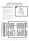
SERVICING INSTRUCTIONS
REPLACING PARTS