


minimum of 10 minutes must be allowed before trying to
relight. If this safety device is continually shuts off the gas it
can suggest a serious problem:
• Contact Gazco
2.8 Do not alter or tamper with the Flue Sure System. Use only
genuine Gazco replacement parts when servicing the system
- refer to the Servicing Section, Replacing Parts.
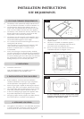
3.1 Flue Pipe Installation
• Open the carton
• Remove the accessory carton and stove unit
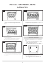
• Decide whether to use top or rear flue exit
The stove is factory built for rear flue exit but it can be
changed to top exit by swapping the flue spigot and
blanking plate located on the stove.
3.2 • Position the stove ensuring all appropriate clearances are
observed
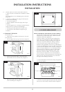
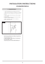
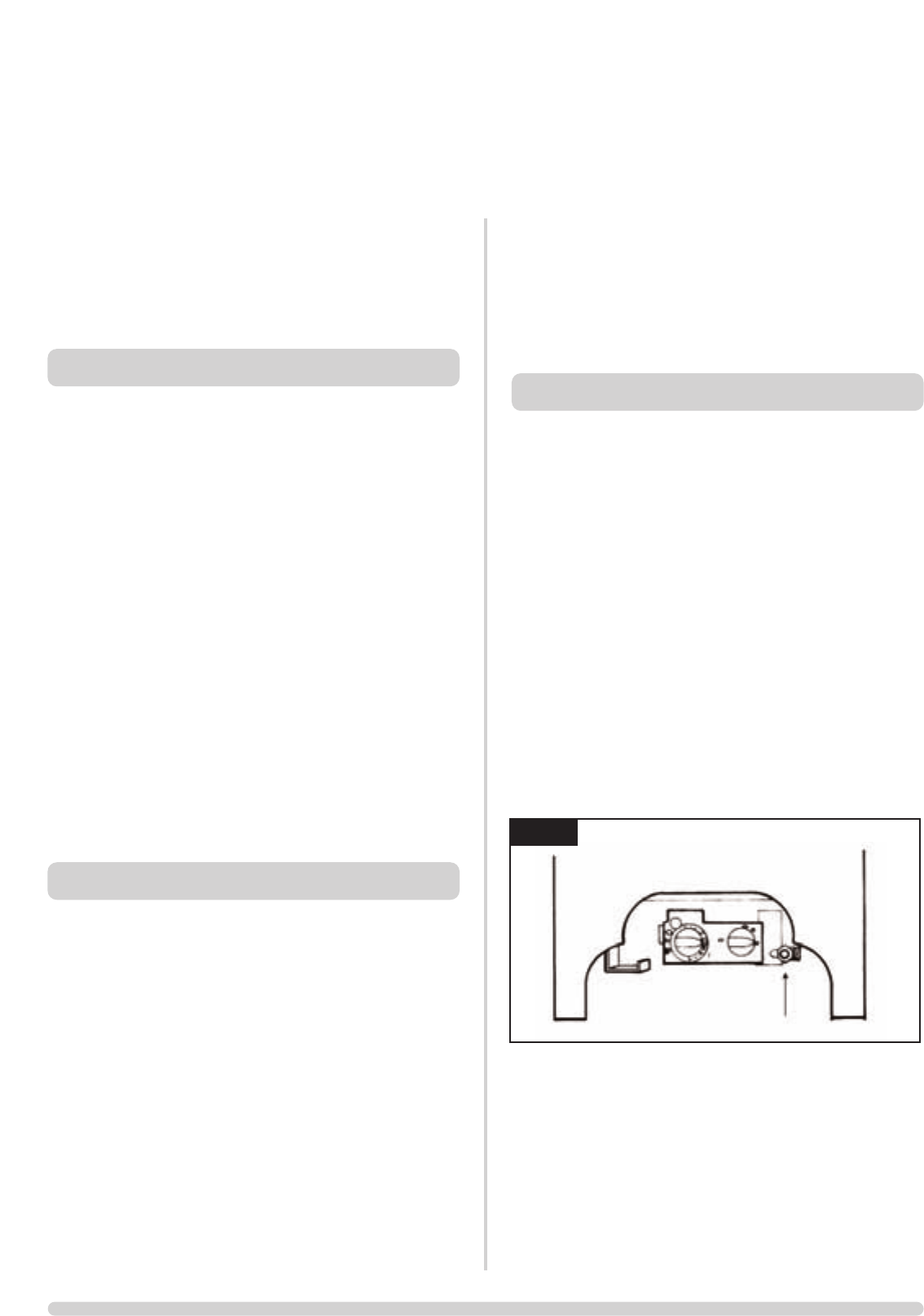
3.3 Having run the gas supply to the stove:
• PURGE THE SUPPLY PIPE
This is essential to expel any debris that can block the gas
controls.
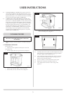
• Connect the gas supply to the 8mm-compression elbow
at the right-hand rear corner of the stove
There is a cutout in the right-hand rear leg to enable a
straight connection to the rear of the stove, Diagram 3. A
gas soundness check must be completed up to the gas inlet
connection.
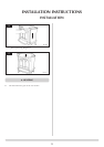
3.4 • Check the pull of the flue system by applying a lighted
smoke pellet to the flue system opening
If there is a definite flow into the chimney, proceed with
the installation. If not, warm the chimney for a few minutes.
IF THERE IS STILL NO DEFINITE FLOW, THE FLUE MAY
REQUIRE ATTENTION - SEEK EXPERT ADVICE
3
AR0934
10
IMPORTANT: ENSURE THAT THE APPLIANCE IS
CORRECTLY ADJUSTED FOR THE GAS TYPE AND
CATEGORY APPLICABLE IN THE COUNTRY OF USE.
REFER TO DATABADGE AND TECHNICAL
SPECIFICATIONS AT THE FRONT OF THIS BOOKLET.
FOR DETAILS OF CHANGING BETWEEN GAS TYPES
REFER TO SERVICING SECTION, REPLACING PARTS
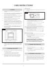
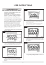
1.1 This stove is fitted with a control valve that can be easily
upgraded to battery powered remote control. There are two
versions of this control which can be obtained through your
local Gazco stockist.
1.2 This upgrade can be fitted before or after installation but if
side clearances are limited then it will be easier to upgrade
the stove before installation. Full instructions are included
with the kit.
1.3 STANDARD REMOTE CONTROL This remote control can
control the gas appliance after the pilot has been lit. It can
turn the main burner on and regulate it from low through to
high and back again. It can turn the main burner off leaving
the pilot burning. GAZCO PART NUMBER 8455.
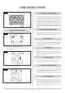
1.4 THERMOSTATIC AND TIMER REMOTE CONTROL This
remote control can control the gas appliance after the pilot
has been lit. In ‘MANUAL MODE’ it can be used to turn the
main burner on and manually regulate it from low through
to high and back again. It can also be used to turn the main
burner off leaving the pilot burning. In ‘AUTO MODE’ it
will automatically regulate the room temperature. In ‘TIMER
MODE’ it will turn the fire on and off according to a pre-set
programme and automatically regulate the room
temperature during two on periods. GAZCO PART
NUMBER 8456
2.1 This appliance must be installed in accordance with the
rules in force, and used only in a sufficiently ventilated
space. Place read these instructions before installation and
use of this appliance.
2.2 All the instructions must be left intact with the user.
2.3 In your own interest, and those of safety, this appliance
must be installed by a competent person in accordance
with local and national codes of practice. Failure to install
the appliance correctly could lead to prosecution.
2.4 This appliance is intended for use on a governed gas
installation and set to the required pressure.
2.5 Keep all plastic bags away from young children.
2.6 Do not place any object on or near to the stove. Allow
adequate clearance above the stove. See diagram 2 page 9.
2.7 The stove is fitted with the Gazco Flue Sure System, which
cuts off the gas supply to the stove in the event of incorrect
flue operation. If the system shuts off the gas supply, this
indicates there is insufficient flue pull. If this happens, a
2. SAFETY PRECAUTIONS
1. CONTROL UPGRADE
INSTALLATION INSTRUCTIONS
INSTALLATION
3. INSTALLATION OF THE STOVE