


22
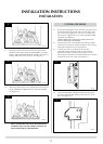
3. PILOT UNIT
The pilot assembly consists of four components, which can
be individually changed, these are:
1) Pilot burner bracket.
2) Pilot injector
3) Electrode
4) Thermocouple.
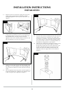
3.1 Open the front door of the appliance and turn off the gas
supply at the isolating device. Remove the glass frame and
logs.
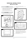
3.2 Remove the two screws securing the pilot burner to the
pilot cover and the two screws securing the cover to the
tray. See diagram 5. The pilot components can now be
individually removed.
AR0819
5
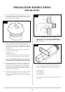
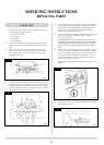
3.3 To remove the pilot injector, undo the compression nut on
the pilot feed pipe and withdraw the injector which will be
hooked onto the olive. When replacing an injector always
ensure it is hooked onto the olive before inserting it into the
pilot burner. See diagram 6, arrow A.
6
AR0820
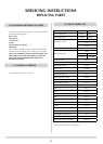
SERVICING INSTRUCTIONS
REPLACING PARTS
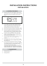
3.4 To remove the electrode, undo the retaining nut, withdraw
the electrode from the pilot burner and disconnect the
ignition lead. When replacing the electrode ensure the
ignition lead is connected with the terminal pointing
downward. See diagram 6, arrow B.
3.5 To remove the thermocouple it will be necessary to remove
the main burner, logs, vermiculite and log support as
described in section 2.
WHEN REMOVING THE THERMOCOUPLE DO NOT
DESTROY THE COMPONENT AS IT WILL BE NECESSARY
TO PREFORM THE NEW COMPONENT TO THE SAME
SHAPE. THIS WILL ASSIST WHEN FITTING THE NEW
PART.
3.6 Once the main burner and pilot cover have been removed,
there is a cover plate beneath the pilot assembly. Remove
the screw and plate. This has been sealed with silicone to
ensure no air enters the firebox. See diagram 6, arrow C.
a) Undo the thermocouple retaining nut from the pilot
burner. See diagram 6, arrow D.
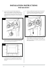
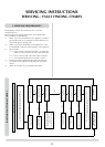
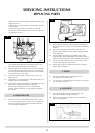
b) Disconnect the inlet pipe at the pressure test point. See
diagram 7.
7
AR1294
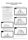
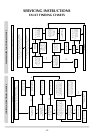
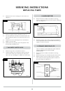
c) Disconnect the external pilot pipe from the brass fitting.
See diagram 8, arrow A.
AR0822
8