


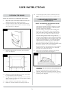
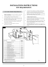
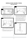
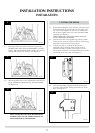
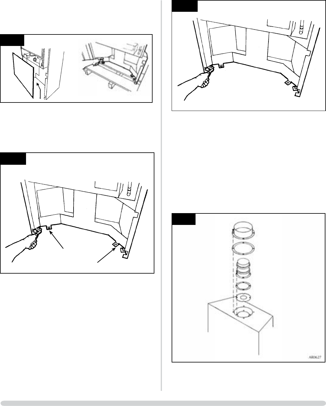
3.3 Remove the lower front panel by gripping the top tag and
pulling gently upwards and out. Locate the two bolts
securing the appliance to the crate base and remove. See
diagram 3.
AR1290/1
3
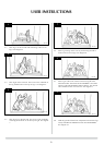
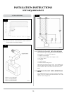
3.4 Gently remove the appliance from the crate and place into
its intended position. Locate the two securing holes in the
base subframe (those previously used to secure the
appliance to the crate), mark the positions on the floor and
place the appliance to one side. See diagram 4
4
AR1292
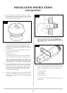
3.5 Drill the two holes and insert the rawl plugs supplied. If the
gas supply is to enter through the floor under the appliance,
now is the time to make the necessary provision for the gas
supply.
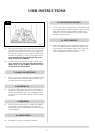
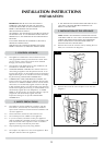
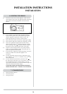
3.6 Place the appliance back into position, level the appliance if
required by adjusting the 3 levelling screws and then secure
in place using the screws supplied. See diagram 5.
13
INSTALLATION INSTRUCTIONS
INSTALLATION
5
AR01292
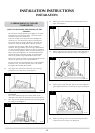
3.7 It will now be necessary to decide upon the flue route and
make the necessary flue connections. Two types of flue
termination are available, a horizontal terminal discharging
on a vertical wall or a vertical terminal discharging above
the roof level. Refer to Section 2 in Site Requirements for
allowable flue configurations in each instance.
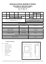
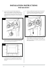
3.8 When the flue configuration and lengths are known, it may
be necessary to fit a flue restrictor. Refer to Technical
Specification on page 8 for the correct restrictor size. This
should be fitted by removing the internal and external
spigots. The restrictor should be located between the
underside of the inner spigot and the air duct. Refer to
diagram 6.
6