


2 2.1 L Hydraulic Pump Installation Instructions
Before you mount the pump, if your boat has an unbalanced cylinder
steering system, you must re-congure the pump to work properly with
the unbalanced cylinder (page 3).
1. After you select a mounting location, determine the mounting
hardware needed for the surface.
Mounting hardware is included with the pump, but it may not be
suitable for the mounting surface.
2. If necessary, purchase the mounting hardware.
3. Hold the pump in the intended mounting location and mark the
locations of the mounting holes on the mounting surface, using the
pump as a template.
4. Using a drill bit appropriate for the mounting surface and selected
mounting hardware, drill the four holes through the mounting
surface.
5. Secure the pump to the mounting surface using the selected
mounting hardware.
notice
Do not attempt to use the autopilot to steer the boat until you bleed all
air from each part of the hydraulic system (page 3).
When adding hydraulic line to the system, use only hose with machine-
crimped or eld-replacable ttings that have a minimum rating of
1000 lbf/in
2
.
Do not use plumber’s tape on any hydraulic tting. Use an appropriate
thread sealant rated for marine use on all pipe threads in the hydraulic
system.
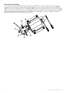
Before you connect the pump to the hydraulic lines, refer to one of these
diagrams to nd the correct place to add the pump and ttings to the
hydraulic system.
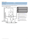
• Single helm without power assist (page 5)
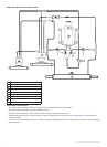
• Dual helm without power assist (page 6)
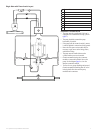
• Single helm with power assist (page 7)
• Five-connector install method (page 8)
The diagrams on pages 5–7 show the recommended pump installation
method, with t-connectors in the hydraulic steering lines of the boat,
using only three ttings on the manifold. However, it is possible to
install the pump using the ve-connector method shown on page 8.
1. Disconnect the necessary lines from the hydraulic system.
2. Add a t-connector to the starboard and port lines of the system.
3. Add hydraulic hose to the unused tting on each t-connector,
sufcient to connect the t-connector to the pump ttings.
4. Connect the starboard line t-connector to the H1 or H2 pump tting.
5. Connect the port line t-connector to the H pump tting that you did
not use in step 4.
6. Install the Shadow Drive to the port or starboard hydraulic line
between the helm and the t-connector.
See the installation instructions provided with your Garmin autopilot
for Shadow Drive installation instructions.
7. Connect the return line from the helm to the Tank tting of the
pump.
8. Install a shut-off valve (page 2) on each hydraulic line that connects
directly to the pump (optional).
9. Insert, tighten, and seal the included plugs in the unused pump
ttings.
1. Disconnect the necessary lines from the hydraulic system.
2. Add a t-connector to the starboard and port lines of the system
between the helm t-connector and the steering cylinder.
3. Add hydraulic hose to the unused tting on each t-connector,
sufcient to connect the t-connector to the pump ttings.
4. Connect the starboard line t-connector to the H1 or H2 pump tting.
5. Connect the port line t-connector to the H pump tting that you did
not use in step 4.
6. Install the Shadow Drive to the port or starboard hydraulic line
between the helm t-connector and the pump t-connector.
See the installation instructions provided with your Garmin autopilot
for Shadow Drive installation instructions.
7. Connect the return line from the helm t-connector to the Tank tting
of the pump.
8. Install a shut-off valve (page 2) on each hydraulic line that connects
directly to the pump (optional).
9. Insert, tighten, and seal the included plugs in the unused pump
ttings.
1. Disconnect the necessary lines from the hydraulic system.
2. Add a t-connector to the starboard and port lines of the system
between the power assist module and the steering cylinder.
3. Add hydraulic hose to the unused tting on each t-connector,
sufcient to connect the t-connector to the pump ttings.
4. Connect the starboard line t-connector to the H1 or H2 pump tting.
5. Connect the port line t-connector to the H pump tting that you did
not use in step 4.
6. Install the Shadow Drive to the port or starboard hydraulic line
between the helm and the t-connector.
See the installation instructions provided with your Garmin autopilot
for Shadow Drive installation instructions.
7. Add a t-connector to the return line between the power assist module
and the helm.
8. Connect the return line from the helm to the Tank tting of the
pump.
9. Install a shut-off valve (page 2) on each hydraulic line that connects
directly to the pump (optional).
10. Insert, tighten, and seal the included plugs in the unused pump
ttings.
Garmin recommends the installation of shut-off valves on each
line connected to the pump. The shut-off valves allow you to easily
disconnect and remove the pump from the hydraulic system without
affecting helm steering. Refer to the diagrams on pages 5–7 to view
ideal shut-off valve placement.
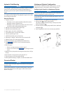
Before you connect the pump to the ECU, you must mount the pump
(page 2) and ECU.
See the installation instructions provided with your Garmin autopilot for
ECU installation instructions.
Connect the two cables from the pump to the ports on ECU marked
DRIVE and FEEDBACK.
The ports are keyed to the appropriate ttings on the cables.