


12
13
920-159-01 (10-03)
920-159-01 (10-03)
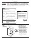
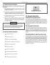
8) Final Installation Checklist
o
Correct line voltage?
o
Chassis deck level?
o
Plenum divider bafe installed?
o
Wall plenum caulked? Level? Flashing?
o
HACR type breaker/fuse?
o
Single circuit only?
o
Ductwork connected?
o
Chassis weather seal in place?
o
Wall thermostat wired correctly?
o
Chassis inserted into plenum?
III. Chassis Operation
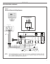
9) Remote Thermostat Control
The chassis requires a simple single stage heat-cool wall thermostat.
Each chassis comes with a terminal strip located in the electrical
control box. All internal chassis wiring (low & high voltage) is factory
ready for 230 Volt operation. For 208 Volt operation a single wire
MUST BE CHANGED ON THE TRANSFORMER. Refer to Figure
8 on page 9.
10) Low Ambient Protection
Each chassis is equipped with Low Ambient Protection in the form of
a suction line thermostat. This thermostat will prevent compressor
operation at low suction line temperatures. Each chassis is also
equipped with a factory installed bellows that will drain water from
the base pan to prevent the fan slinger from freezing during winter
weather.
11) Heating Defrost (Heat Pump Models Only)
All Heat Pumps have a passive heating defrost system. Defrost
occurs as needed and automatically switches to electric heat during
defrost. When the outdoor ambient temperature drops below a 45°F
factory setting, the chassis automatically switches to electric heat.
As outdoor ambient temperatures rise above 45°F, the chassis
returns to the heat pump mode. The changeover temperature
is user adjustable from approximately 32°F - 55°F. The defrost
thermostat may also be used to lock out the compressor in an
emergency heat situation.
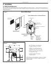
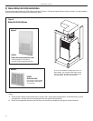
7) Chassis Final Connections
With the chassis in place, you are now ready to begin chassis
connections:
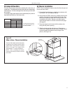
A. Move the thermostat switches to "OFF" and "AUTO." This
will keep the thermostat from cycling the chassis until nal
connections are complete.
B. Connect the ductwork onto the 10" collar. Plastic wireties (eld
supplied) are suggested to secure the ductwork in place. Use
2 wire ties, one for each inner and outer ex duct sleeve.
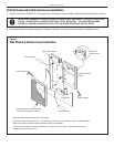
D. For 208 Volt power only: you must move the transformer wire
as shown in Figure 8, Page 9.
E. Review the Final Installation Checklist on Page 12 before
replacing the power quick disconnect, reconnecting power
to the chassis, plugging in the remote thermostat harness, or
operating the chassis.
Electrical shock and moving parts hazard can cause injury
or death. If you have not done so, pull out the disconnect
head found on the front of chassis before continuing instal-
lation! Disconnect external power at the breaker.
RT2 Digital Thermostat