


10
11
920-159-01 (10-03)
920-159-01 (10-03)
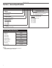
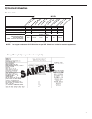
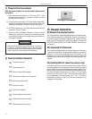
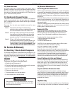
5) Indoor Airow Data
The Vert-I-Pak A series units must be installed with a free return air
conguration. The table below lists the indoor airow at corresponding
static pressures. All units are shipped from the factory and are rated
at low speed.
To change to high speed replace the low speed lead (blue) with the
high speed lead (black) on the blower relay.
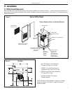
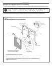
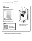
6) Chassis Installation
NOTE: Prior to installing the chassis, ensure that the drain pan and
line are free from debris.
A. Ensure that the wall plenum is installed in accordance with
the VPAWP1-8/1-14 Installation Manual.
B. Ensure that the VPDP1 drain pan is installed correctly (see
page 8). Using the 3/4" plugs supplied with the pan, plug
the unused condensate drain hole. Connect a drain to the
condensate exit location. Be sure to use teon tape or
approved pipe sealant on all drain connections and plugs
(see page 8).
C. Place the chassis into the closet with the outdoor side
facing the wall plenum opening.
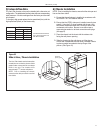
D. Slide the chassis into the wall plenum until the plenum
divider seal is established and the factory-installed chassis
to plenum gasket has sealed to the top ange of the
plenum. (See Figure 10)
All values listed are inches
W.C. with a wet indoor coil
with lter installed.
2
3
/8
Chassis to
plenum gasket
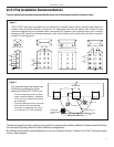
The Vert-I-Pak chassis must be inserted into
the wall plenum so that the plenum divider
gasket makes contact with the condenser
baffle in the unit. The chassis will fit
approximately 2
3
/
8
" into the wall plenum.
NOTE: Prior to installing the chassis,
ensure that the drain pan and line are free
from debris.
Slide-in View / Chassis Installation
Figure 10
VEA/VHA24K
Low High
.1” ESP 750 815
.2” ESP 725 780
.3” ESP 700 745
.4” ESP 675 700