


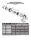


4
1-1/2”
GALVANIZED
PIPE
WELL POINT
CHECK
VALVE
1-1/2” RIDGED
PVC PIPE
1-1/2 RIDGED
PVC PIPE
1-1/2” PVC
ADAPTER
1-1/2” FOOT
VALVE
1-1/2” PVC
ELBOW
WELL
SEAL
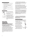
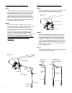
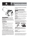
WELL POINT
INSTALLATION
1-1/2” DISCHARGE PORT
1-1/2”
GALVANIZED
PIPE
WELL POINT
1-1/2” PVC
ELBOW
MULTIPLE WELL
POINT INSTALLATION
CHECK
VALVE
TO
PUMP
TO SPRINKLE
R SYSTEM
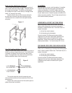
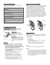
PRIMING PORT
1-1/2” SUCTION PORT
DRAIN PLUG
1-1/2” PVC
ELBOW
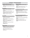
A. Suction Port Connection (Figure 4)
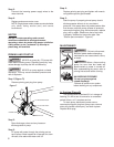
Step 1:
Attach the foot valve or well point to pipe assembly
and lower pipe and foot valve until it is at least fi ve
feet below the water level. If you are using a well,
temporarily clamp the pipe to the well casing to
prevent the pipe from sliding into the well. If well is
in a 4" or 6" casing, use a well seal at the surface.
Never use a suction pipe size smaller than the size
of the suction port on the pump.
Step 2:
Connect the necessary elbows, fi ttings, check
valves, and pipe from the water to the pump suction
port on front of pump. When using PVC, pre-
assemble pipe and fi ttings to the pump BEFORE
applying PVC cement to ensure proper cuts and
inventory. Use tefl on tape on all male threads,
wrapping clockwise (when facing pipe) 1 to 2 layers
thick. Tighten all threaded pipe fi ttings until snug.
DO NOT OVER TIGHTEN PIPE AND FITTINGS!!
Tighten joints hand tight plus 1/2 turn with
pipe wrench.
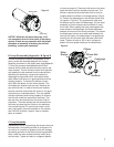
B. Discharge Port Connections (Figure 5)
Step 1:
Thread male adapter or pipe nipple into discharge port
on top of pump. (Use tefl on tape on thread)
Step 2:
Connect pipe between the sprinkler manifold and
the pump discharge. Discharge pipe size should
increase with long pipe runs. Discharge pipe size
may equal discharge port size for distances up to
100'. Increase discharge pipe size by one size for
distances of 100' to 300'. For 300' to 600', increase
pipe size by two sizes. This will reduce pressure
loss caused by friction.
Step 3:
Tighten all threaded pipe connections with pipe wrench
until snug. Do not over tighten.
PRIMING PORT
1-1/2" SUCTION PORT
DRAIN PLUG
1-1/2" DISCHARGE PORT
Figure 4
Figure 5