


7
NOTICE: While this will drain the pump, it will
not necessarily drain all other parts of the piping
system. If there are any concerns with the proper
procedure or necessity of draining the suction
plumbing, contact your contractor.
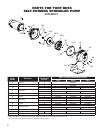
B. Pump Disassembly (Appendix I & Figure 9)
In order to access the internal components of the
pump, review the exploded diagram of the pump
assembly as shown on the repair parts page(Appendix
I). Drain the pump as described above and then
remove the four bolts that hold the pump case to the
motor bracket. This will allow the motor and hydraulic
sub-assembly to be removed from the case without
disturbing the plumbing. Locate and inspect the
diaphragm and grommet which are internal water
seals. Make sure they are in good condition and are
working properly. To remove the diffuser, loosen
the 3 bolts that attach it to the motor bracket. This
will expose the impeller and eye-seal. Remove the
eye-seal and then, in order to remove the impeller,
securely hold the motor shaft with a pair of vice grips
to prevent any unwanted rotation. Turn the impeller
counter-clockwise (when facing impeller) to remove
and this will reveal the mechanical shaft seal. This
seal can then be removed from the motor shaft for
inspection. The motor bracket can be removed from
the motor by removing the 4 bolts on the backside
of the motor bracket. To remove the ceramic shaft
seal, press gently from the backside on the ceramic
and it will fall out easily. Inspect, clean or replace
parts as needed.
C. Pump Assembly
Reassemble unit by fi rst pressing the ceramic seal into
the seal plate. Use rubbing alcohol as a lubricant. Do
not use an oil, vaseline or grease as this will damage
the sealing surfaces of the shaft seal during operation.
Next, install the motor bracket onto the motor using
the four bolts. Tighten the bolts in a diagonal pattern
to insure a proper fi t. Place the shaft seal on the motor
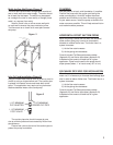
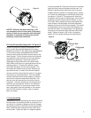
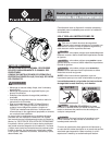
shaft and then install the impeller and eye-seal. The
diffuser is positioned by three bolts that can only be
installed when the diffuser is oriented properly (Figure
9). Position the diaphragm on the diffuser suction eye.
(as shown in Figure 9). The grommet will slide over
the diffuser eye on top of the diaphragm. Lift the motor
assembly up into the pump case and attach it using
the 4 bolts. When seating the pump case against the
motor bracket, the diaphragm should be captivated
between them around the entire perimeter. This allows
the diaphragm to serve as a water seal between the
two cast iron parts. If the diaphragm is not positioned
correctly the unit will leak once the case is fi lled with
water. Tighten all bolts to 185 in-lbs in a diagonal
pattern to insure proper seating of all components.
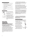
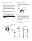
Drain Plug
Priming Port
Diffuser
Motor
Bracket
Diffuser Bolt
Diffuser Bolt
Grommet
Diaphragm
Figure 8
Figure 9