


3
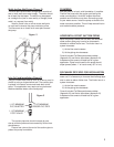
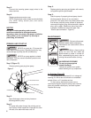
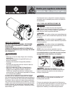
Lake Or Pond Installation (Figure 3)
Using a surface water source such as a lake or pond is
similar to using a single shallow well. The suction pipe
is placed in the water source and leads back to the
pump. This application may require a long horizontal
distance between water source and pump.
The suction pipe size should increase by one
size to minimize pressure loss caused by friction from
pipe distance.
Place a foot valve at the end of the suction pipe to
protect the pump from debris.
1-1/2" MINIMUM
RIDGED PVC PIPE
1-1/2" MINIMUM
PVC ADAPTER
1-1/2" MINIMUM
FOOT VALVE
Figure 3
PLUMBING
Bolt the pump to a level, solid foundation, if possible.
Position the pump with the suction port facing the
water source pipe(s). Avoid 90º angles whenever
possible and minimize turns when connecting pump
to your water source. Install the pump as close to the
water source as possible. This will help reduce friction
and maximize water pressure.
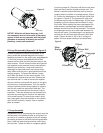
HORIZONTAL OFFSET SUCTION PIPING
When the pump is offset from the well, the horizontal
offset suction piping may have to be increased in
diameter to reduce friction loss. The friction loss in a
system increases:
1.) As the fl ow rate increases
2.) As the piping size decreases
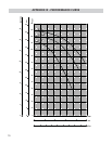
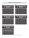
Consult included Turf Boss performance tables
(Appendix III) and friction loss tables (Appendix IV)
to determine the amount of head lost for a given
application. Pipes from the well to the pump should
slope upward (about 1” of rise for every 30” of run).
DISCHARGE PIPE SIZES FOR INSTALLATION
When the pump is located at a distance from points of
water use, it is necessary to increase the discharge pipe
size in order to reduce friction loss. The friction loss in a
system increases:
1.) As the fl ow rate increases
2.) As the piping size decreases
Consult included Turf Boss performance tables
(Appendix III) and friction loss tables (Appendix IV)
to determine the amount of head lost for a given
application.
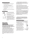
Figure 2
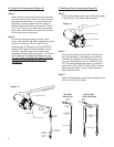
Multi-shallow Well Points (Figure 2)
The multi-point shallow well confi guration consists of
two or more wells as a water supply. The wells should
be at least fi ve feet apart. The wells may be spaced
as a straight line (two or more wells), a triangle (three
wells), or a square (four wells).
Install a check valve or a fi ne screen well point
on each well to ensure the pump maintains prime.
The fl ow arrow on a check valve must point toward
the pump.