


19
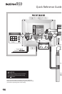
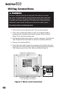
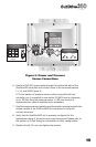
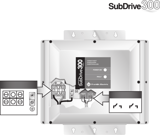
6. Feed the 230 VAC power leads through the bottom left side of the
SubDrive300 controller and connect them to the terminals marked
L1, L2, and GND (Figure 3).
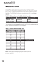
A 10-foot section of pressure sensor cable is provided with the
controller, but it is possible to use similar 22 AWG wire for distances
up to 100 feet from the pressure sensor. A 100-foot section of
pressure sensor cable is available as an accessory.
7. Feed the pressure sensor leads through the smaller opening located in the
bottom middle of the SubDrive300 unit and press on the quick
connect terminals.
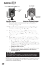
8. Verify that the SubDrive300 unit is properly confi gured for the
horsepower rating of the motor and pump being used. Please refer to
the section on Pump Sizing for information on drive confi guration.
9. Replace the lid. Do not over-tighten the screws.
Figure 3: Power and Pressure
Sensor Connections
PRESSURE
SENSOR
SHUT-OFF
INT
FAN
INV
FAN
PFC
FAN
NO NO
COM
RELAY
SW2
SW1
O
N
From Power Source
L2L1
(Input)
BlkRed GrnWh
Sensor Connection
PRESSURE
SENSOR
PRESSURE
SHUT-OFF