18
Wiring Connections
1. Verify that the power has been shut off at the main breaker.
2. Verify that the dedicated branch circuit for the SubDrive300 is
equipped with a properly-sized circuit breaker. Refer to Table 2
(Page 13) for minimum breaker size.
3. Use the appropriate strain relief or conduit connectors. Type B liquid
tight fi ttings are recommended for maximum weather protection.
4. Remove the SubDrive300 lid.
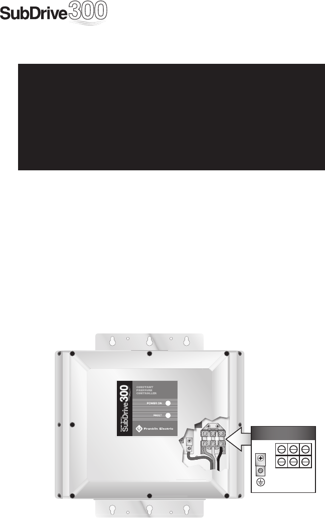
5. Feed the motor leads through the opening on the bottom right side
of the unit and connect them to the terminal block positions marked
GND (Green ground wire), Red, Yellow and Black (Figure 2).
Figure 2: Motor Lead Connections
▲ WARNING
!
Serious or fatal electrical shock may result from failure to connect
the motor, the SubDrive300, metal plumbing and all other metal near
the motor, or cable to the power supply ground terminal, using wire
no smaller than motor cable wires. To reduce risk of electrical shock,
disconnect power before working on or around the water system.
Do not use motor in swimming areas.
PRESSURE
SENSOR
SHUT-OFF
INT
FAN
INV
FAN
PFC
FAN
NO NO
COM
RELAY
SW2
SW1
O
N
Output to Motor
Red Yel Blk
(Brn) (Blue) (Blk)
(Output)


