


www.fmiproducts.com
108794-01G 9
This appliance may be vented through a
manufactured chimney system or a masonry
chimney using a B-vent adapter or a chim-
ney liner system if all are listed, inspected
and approved by local codes and/or building
authorities.
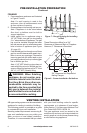
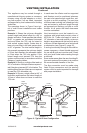
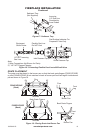
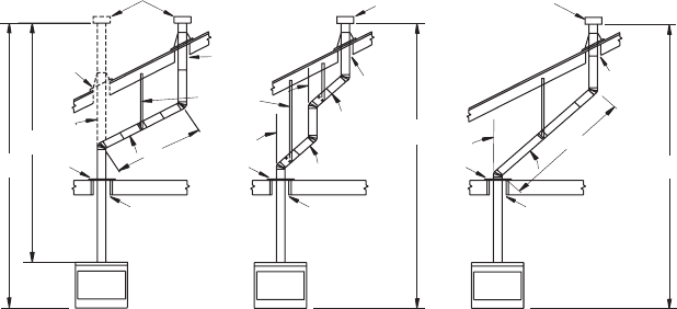
The examples shown in Figure 9 are typi-
cal of most B-vent installations and codes
practices.
Example1: Shows the minimum allowable
system height and lateral offset for a 60° or
greater inclination. Code species that offsets
at 60° or greater are considered horizontal
and must follow the 75% rule for lateral to
total vertical system height. Codes also al-
lows only one offset in the total system when
at 60° or greater. The total vertical height in
this example represents the minimum height
of 8 feet and therefore the allowable lateral
is 6 feet when the 75% rule applies. If the
lateral length must exceed 75% then the
system must be sized in accordance with the
Category I venting tables.
Example2: Shows a multiple offset each at
45° of inclination. Multiple offsets are permit-
ted if they do not exceed 45° of inclination. The
total lengths of the two offsets are not required
to meet the 75% allowable rule.
Example3:Shows a single offset at 45° of
inclination and therefore the lateral length at
10 feet of offset does not have to meet the
75% rule.
Maintain
Listed
Clearance
Maintain
Listed
Clearance
12' Min.
12' Min.
45°
45°
6'
8'
12' Min.
60°
45°
Position
Firestop
Position
Firestop
Position
Firestop
Listed
Vent Cap
Listed
Vent Cap
Listed
Vent Cap
Maintain
Listed
Clearance
Maintain
Listed
Clearance
Maintain
Listed
Clearance
Maintain
Listed
Clearance
Support Each
Lateral At
Least Every
6 Feet
Maintain
Listed
Clearance
10'
EXAMPLE 3EXAMPLE 2
EXAMPLE 1
Figure 9 - Typical B-Vent Conguration
VENTING INSTALLATION
Continued
In each case the offsets must be supported
and restops must be positioned wherever
the vent must pass through a sub-oor, ceil-
ing joist or an attic overhang. The vent pipe
must terminate vertically into a listed type vent
cap and extend a sufcient height through
an approved roof ashing, roof jack or a roof
thimble. At all points the listed clearances
must be maintained.
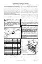
Vent terminations must be located in ac-
cordance with height and proximity rules of
NFPA No. 54. These rules apply to vents at
12" diameter or less and require a minimum
height in accordance with the roof pitch and a
minimum of 8 feet distance from a vertical wall
or obstruction (see Figure 10, page 10).
If venting horizontally through a side wall be-
comes necessary, a listed thimble approved
for use with B-type vent must be used. Check
with your local codes before venting through
a side wall.
Some codes areas allow the use of existing B-
type vent systems if the system is at or above
the recommended diameter of the ue.
The ue connection must be made using
listed B-type connectors and the existing
system must be code inspected for damage
and proper installation.