


www.fmiproducts.com
108794-01G 11
FIREPLACE INSTALLATION
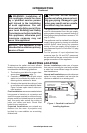
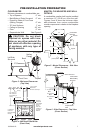
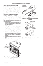
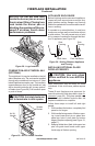
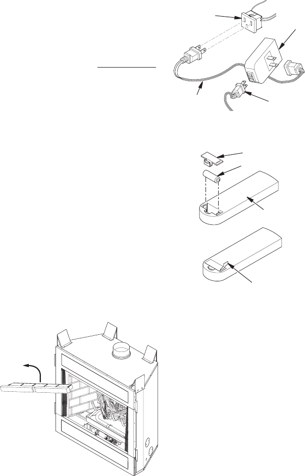
Figure 12 - Removing Front Refractory
Access Panel (P325E/VP325E Model
Shown)
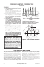
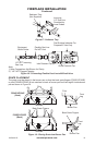
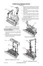
Figure 13 - Installing the WRC Remote
Receiver
Fireplace
Receptacle
Remote
Control
Receiver
Extension
Cord
Ignition Module
Plug
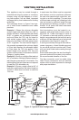
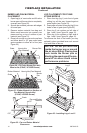
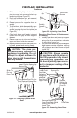
Figure 14 - Installing Battery into Back of
Handset
Pull to Remove
Insulation Tab
Battery Cover
12 Volt Battery
Back of
Handset
WALL SWITCH INSTALLATION
The installation of a wall switch allows you
to activate the gas control valve and turn the
replace on and off. The wall switch is to be
connected to the incoming 120 volt regular
household wiring that supplies the electricity
to the replace. Refer to Wiring Diagram,
page 21.
OPTIONAL REMOTE CONTROL
INSTALLATION(ModelWRC)
Note: If using optional wireless hand-held
remote control, wall switch must be in ON
position to be operational. The remote control
then becomes the switching mechanism for
replace operation.
1. Remove front refractory access panel by
lifting up and angling out of rebox open-
ing (see Figure 12).
2. WRC model receiver does not require a
battery. Receiver can be installed by rst
plugging short extension cord into replace
receptacle. Plug receiver unit into exten-
sion cord. Finally, plug ignition module plug
into receiver unit (see Figure 13).
3. Activate remote handset battery by re-
moving insulating tab on back of handset
(see Figure 14). Battery is included pre-
installed.
4. Once battery is activated, unit is ready to
use.
5. Replace front refractory access panel.