


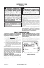
www.fmiproducts.com
108794-01G 7
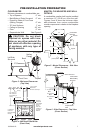
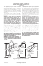
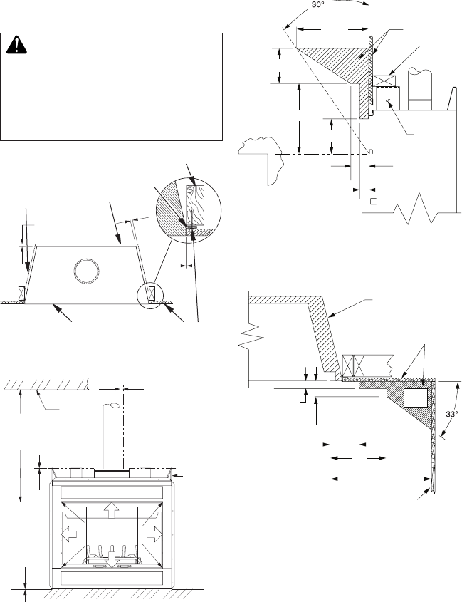
PRE-INSTALLATION PREPARATION
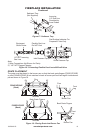
Figure 3 - Minimum Clearances
(Top View)
0"
0" Clearance
Nailing
Flange
Front Face
Left Side
Surround
Back
Drywall
2 x 4 Stud
Figure 4 - Minimum Clearances
(Front View)
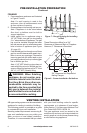
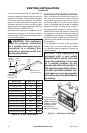
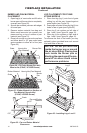
MANTEL CLEARANCES AND WALL
DETAILS
A combustible mantle shelf maybe installed
a maximum 12" (22.90 cm) from the wall.
Figures 5 and 6 show the minimum allow-
able distances from various combustible
mantle components in relation to the replace
opening.
Figure 5 - Mantel Clearances - Side View
(Cross Section)
Figure 6 - Side Clearances - Top View
(Cross Section)
*
*
**
42" (10.67 cm)
Min. Clearance
from Opening to
Ceiling
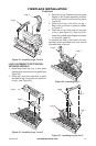
0" Clearance
Ceiling
1" (2.5 cm) Min.
Clearance to
"B" Vent's Outer Pipe
Required
Air Spaces
are Indicated
with an "
*
".
Do Not
Pack with
Insulation or
Any Other
Material
DO NOT BLOCK
OR OBSTRUCT
OPENINGS
0" Clearance
to Wood or
Noncombustible
Flooring
Spacer
3" (7.6 cm)
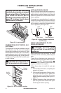
1
1
/2"
(3.8 cm) Max.
8" (20.3 cm)
6" (15.2 cm)
13" (33 cm)
12"
(22.9 cm)
Combustible
Materials
Header
1
1
/
2
" (3.8 cm)
Max.
3" (7.6 cm)
Max.
6" (15.2 cm)
Max.
9"
(22.86 cm)
12"
(30.48 cm)
Outer Surround
Combustible
Material May
Be Used
TOP VIEW
SAFE
ZONE
Perpendicular
Wall
CLEARANCES
Minimum clearances to combustibles are:
• Top of Spacers 0" min.
• Back/Sides of Outer Surround 0" min.
• Drywall to Sides of Front Face
(Nailing Flanges) 0" min.
• “B” Vent Surfaces 1" min.
• Ceiling to Opening 42" min.
• Floor 0" min.
• Perpendicular Wall See Figure 6
CAUTION: Do not block
required air spaces with insu-
lationoranyothermaterial.Do
not obstruct effective opening
of appliance with any type of
facingmaterial.