


www.fmiproducts.com
108794-01G 13
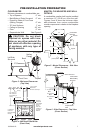
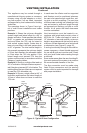
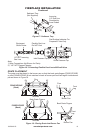
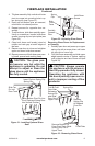
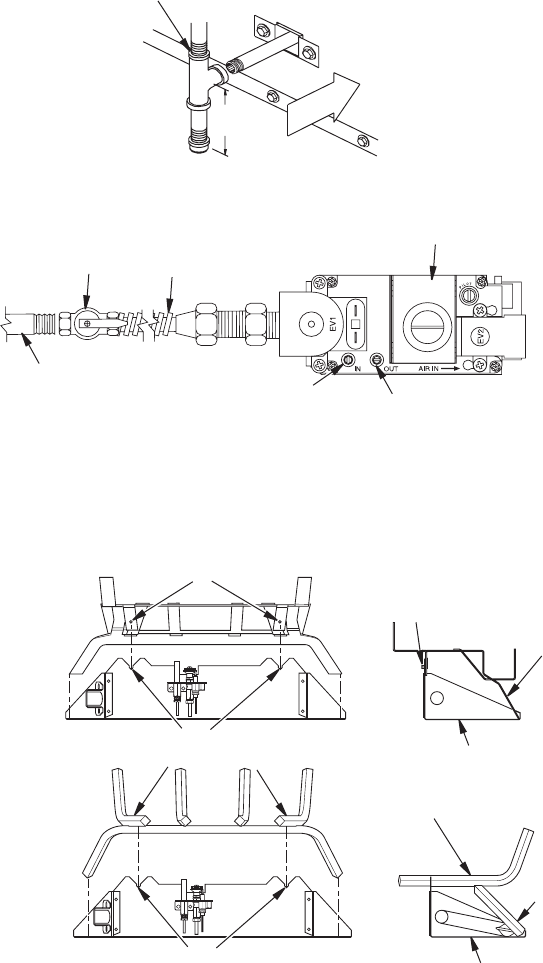
3" Min.
(7.6 cm)
Side Wall
Of Appliance
Incoming
1/2" Gas Line
Permitted by
Local Codes
Sediment Trap
(Not Supplied)
Figure 17- Sediment Trap
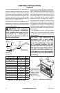
FIREPLACE INSTALLATION
Continued
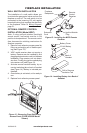
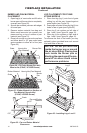
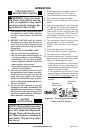
Figure 18 - Connecting Flexible Gas Line to Millivolt Valve
1/2" NPT Incoming
Gas Line
Inlet Pressure Tap
Outlet Pressure Tap
Equipment
Shutoff Valve
Flexible Gas Line
Do NOT Kink
Note:
1) Wire Connections Not Shown for Clarity
2) * 1/8" NPT Plugged Tapping
Red Surface Indicates For
Propane/LP Use Only
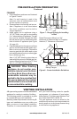
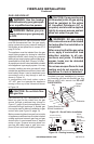
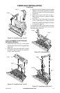
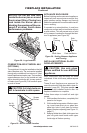
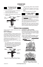
GRATE PLACEMENT
The grate must be placed in the burner pan so that the back grate ngers (P325E/VP325E)
or pins (P324E/VP324E) t into notches on back of burner pan and front legs t inside burner
pan as shown in Figure 19.
Figure 19 - Placing Grate into Burner Pan
P324E/VP324E
(Back)
P325E/VP325E
(Back)
Pins
Notches
Pins
Notches
Back Grate Fingers
Back Grate Fingers
Burner Pan
Burner Pan
Front
Leg
Front
Leg