


www.fmiproducts.com
108794-01G12
GAS LINE HOOK-UP
WARNING: Gas line hookup
shouldbedonebyyourgassuppli-
eroraqualiedserviceperson.
WARNING: Before you pro-
ceed,makesureyourgassupply
is OFF.
The appliance and it’s individual shutoff valve
must be disconnected from the gas supply
piping system during any pressure testing of
that system at test pressures in excess of 1/2
psig (3.5 kPa).
The appliance must be isolated from the gas
supply piping system by closing its individual
equipment shutoff valve during any pressure
testing of gas supply piping system at test pres-
sures equal to or less than 1/2 psig (3.5 kPa).
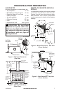
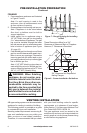
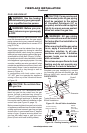
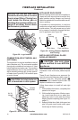
An equipment shutoff valve has been included
in the appliance’s gas supply system. You may
consider installing an extra gas shutoff valve
outside the appliance’s enclosure (check with
local codes) where it can be accessed more
conveniently with a key through a wall as
shown in Figure 15.
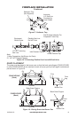
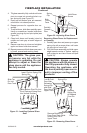
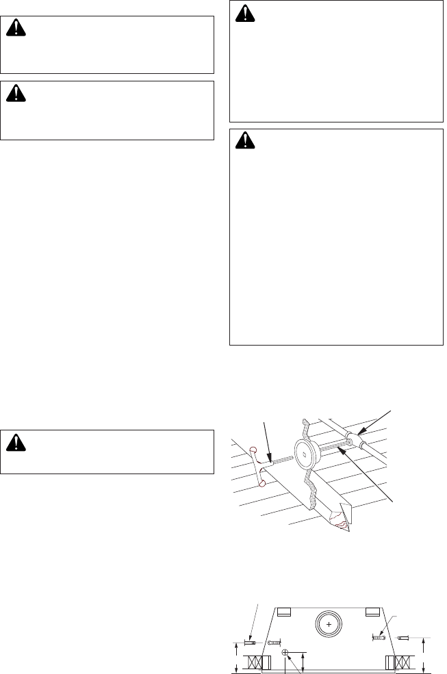
In conformance with local codes, route a
1/2" NPT gas line towards the appliance
coming in from any of the 3 directions shown
in Figure 16.
CAUTION:Donotkinkex-
iblegasline.
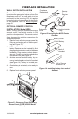
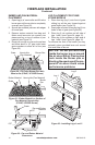
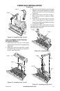
FMI PRODUCTS, LLC recommends that a
black iron gas line be routed from the gas
source, through a sediment trap (shown in
Figure 17, page 13) and into appliance. Once
connected through appliance, a exible gas
line may be used for ease of installation to gas
control valve (see Figure 18, page 13).
Before connecting black iron gas line to inside
of appliance a sediment trap must be included
outside appliance between gas line and gas
shutoff valve. It must extend down 3" beyond
center of pipe. Prepare incoming black iron
gas line with teon tape or pipe joint com-
pound (Check with local building codes).
FIREPLACE INSTALLATION
Continued
CAUTION:Compoundsused
onthreadedjointsofgaspiping
shallberesistanttotheaction
of Liqueed Petroleum (LP or
propane)andshouldbeapplied
lightlytoensureexcesssealant
does not enter the gas line.
WARNING: All gas piping
andconnectionsmustbetested
forleaksaftertheinstallationis
completed.
After ensuring that the gas valve
ison,applyacommercialleak
detection solution to all con-
nectionsandjoints.Ifbubbles
appear, leaks can be detected
and corrected.
Donotuseanopenameforleak
testing and do not operate any
applianceifaleakisdetected.
Complete your gas installation by connect-
ing incoming gas line with exible gas line.
Secure tightly with wrench but DO NOT
OVERTIGHTEN.
Figure 15 - Shutoff Valve Installation
Typical Exterior Wall Gas
Shutoff Installation
Key
Extension
Shutoff
Valve
Figure 16 - Routing Incoming Gas Line
8
3
/
8
"
10
5
/
8
"
1/2" NPT Incoming
Black Iron Gas Line
Flexible
Gas Line
(1 Provided)
Can Be
Extended Out
Either Side
7"
7"
Alternate Gas Supply
Through Sub-Floor