


www.fmiproducts.com
108796-01UT 11
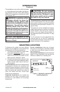
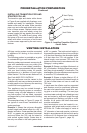
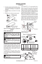
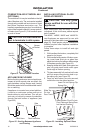
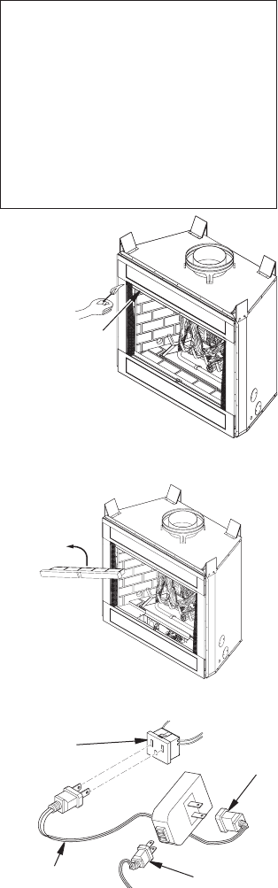
CHECKING FOR PROPER VENTING
After completing and checking electrical,
gas and vent connections, follow the lighting
instructions and allow the main burner to run
for approximately 5 minutes. Hold a lighted
match or cigarette near the top edge of re-
place opening and play it along entire length
of opening (see Figure 12). Proper venting
should tend to draw the ame or smoke into
the appliance. Improper venting or escaping
of spillage of burned gas, is indicated when
the match ickers or goes out. Smoke from a
cigarette will also tend to disperse away from
the appliance.
If the appliance is found to be improperly
venting, shut it off and notify your installer
or a qualied service agency to inspect the
venting system.
VENTING INSTALLATION
Continued
Check this area
along entire top
edge of replace
opening. Smoke
or ame should
be drawn into
appliance opening.
Figure 12 - Checking for Spillage
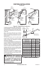
INSTALLATION
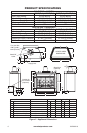
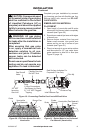
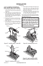
Figure 13 - Removing Front Refractory
Access Panel
Figure 14 - Installing WRC Remote Receiver
Fireplace
Receptacle
Remote
Control
Receiver
Extension Cord
Ignition
Module Plug
NOTICE: This appliance is
equipped with a vent safety
shutoff switch which will shut
downtheapplianceinthecaseof
aventingproblem.Donotbypass
theventsafetyswitch.Iftheappli-
anceshouldshutdown,contacta
qualiedinstaller,serviceagency
or your gas supplier to have the
ventinspectedbeforeoperating.
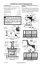
WALL SWITCH INSTALLATION
The installation of a wall switch allows you
to activate the gas control valve and turn the
replace on and off. The wall switch is to be
connected to the incoming 120 volt regular
household wiring that supplies electricity to
the replace. Refer to wiring diagram in this
manual on page 18.
OPTIONAL REMOTE CONTROL
INSTALLATION(ModelWRC)
Note: If using optional wireless hand-held
remote control, wall switch must be in the ON
position to be operational. The remote control
then becomes the switching mechanism for
replace operation.
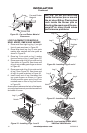
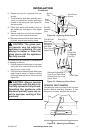
1. Remove front refractory access panel by
lifting up and angling out of rebox open-
ing (see Figure 13).
2. The WRC model receiver does not require
a battery. Receiver can be installed by
plugging the short extension cord into
replace receptacle. Plug receiver unit
into extension cord. Plug ignition module
plug into receiver unit (see Figure 14).