


www.fmiproducts.com
124979-01C 17
INSTALLATION
Continued
WARNING: Read and fol-
Installation should be done by
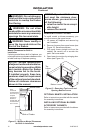
WARNING: Do not connect
this switch to any electrical
1. Remove jumper wire from control valve
(see Figure 20, page 16).
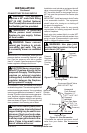
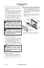
2. Connect one terminal of 25 ft. wire to the
“TH” terminal on the control valve. Con-
nect other terminal to the “THTP” terminal
on control valve. See Figure 22.
3. Route the 25 ft. wire to a convenient loca-
tion to mount your wall switch (no outside
walls).
WARNING: Do not connect
-
IMPORTANT: The wire may be shortened but
must not be lengthened.
4. Connect one bare wire end to each of the
terminals of the provided wall switch.
5. Install the wall switch and cover in the
wall.
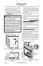
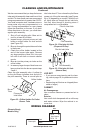
INSTALLING LOG SET AND SCREEN
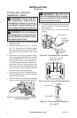
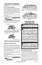
1. Remove log packaging material and
discard packaging. Gently place log over
burner (see Figure 25). Do not allow log to
contact ame. If ame contacts log, soot
will be created.
2. Reattach screen by placing notches in
screen frame over shoulder screws and
pushing down.
Log
Shoulder
Screw
Screen
Figure 25 - Installing Log and Screen
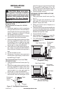
8. Move temperature adjustment back and
forth to insure the bimetal is free from re-
strictions.
9. Replace cover onto base. (Upon installa-
tion, thermostat must be allowed to sta-
bilize at room temperature for a minimum
of 30 minutes for proper operation).
10. Set temperature adjustment to desired
setting. This thermostat has been elec-
tronically calibrated at the factory. No
adjustment or leveling is necessary.