


www.fmiproducts.com
124979-01C16
WARNING: Read and fol-
Installation should be done by
WARNING: Do not connect
this thermostat to any electrical
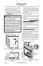
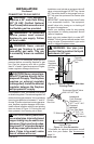
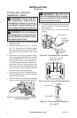
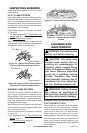
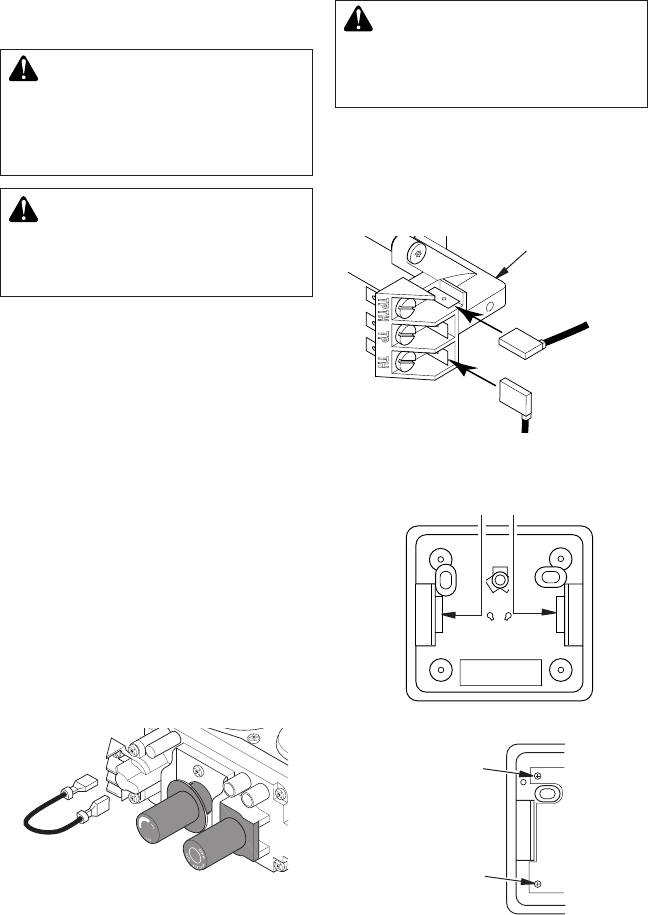
1. Remove jumper wire from control valve
(see Figure 20).
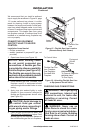
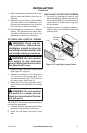
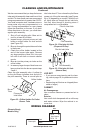
2. Connect one terminal of 25 ft. wire to
the “TH” terminal on the control valve.
Connect the other terminal to the “THTP”
terminal on the control valve. See Figure
22.
3. Route the 25 ft. wire to a convenient loca-
tion to mount your thermostat (no outside
wall). IMPORTANT: The wire may be
shortened but must not be lengthened.
The thermostat should be mounted 54"
above the oor in a location where there
is good air circulation. Avoid heat sources
such as lamps, direct sunlight, replace
or heat and air conditioning ducts.
4. Gently remove cover of thermostat from
base. Grasp sides of cover rmly and pull
to separate from base.
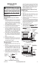
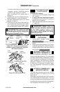
5.
Feed electrical wires through rectangular
slots on each side of base (see Figure 23).
INSTALLATION
Continued
Figure 23 - Back View of Thermostat Base
Feed wires through
rectangular slots
W
R
Figure 24 - Thermostat Base Terminals
“W” and “R”
Terminal “W”
Terminal “R”
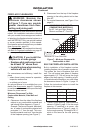
Figure 22 - Connecting Wire Terminals
To Wall
Thermostat
or Switch
To Wall
Thermostat
or Switch
Control Valve
WARNING: Do not con-
nect the thermostat to a power
6. Connect one bare wire end to each termi-
nal (“W” and “R”) of the thermostat base
(see Figure 24).
7. Install base onto wall with provided
screws.
Figure 20 - Disconnecting Jumper Wires
From Control Valve