


10
10
1
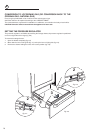
YOU MUST USE STABILITY
ANTI TIP BRACKET TO
PREVENT UNIT FROM
TIPPING.
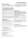
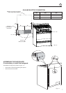
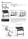
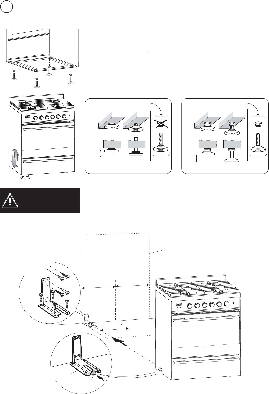
ANTI-TIP STABILITY DEVICE INSTALLATION INSTRUCTIONS
1. The anti-tip bracket has to be attached as shown on fi gure below (only rear left side),
it has to be fi xed on the fl oor OR on the rear wall by no. 4 (four) suitable screws (not
supplied). Alternatively the anti-tip bracket can also be fi xed on the fl oor AND on the
rear wall by no. 8 (eight) suitable screws (not supplied).
2. After fi xing the anti-tip bracket, slide range into place. Be sure the rear left foot slides
under the anti-tip bracket attached.
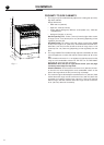
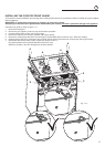
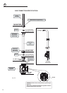
LEVELLING THE RANGE
The range is equipped with 4 LEVELLING FEET and may be levelled by screwing or
unscrewing the feet (fi gs. 1.6 - 1.7).
It is important to observe the directions in fi gures 1.6, 1.8a, 1.8b.
Fig. 1.8bFig. 1.8a
Fig. 1.7
Fig. 1.6
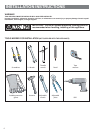
Supplied with the range
in a separate kit
Supplied with the range
in a separate kit
0”
0 mm
+ 5/16”
+ 8 mm
+ 5/16”
+ 8 mm
+ 11/16”
+ 17.5 mm
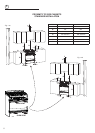
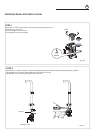
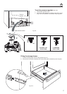
Fig. 1.9
Dotted line showing the position
of the range when installed
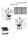
ANTI-TIP STABILITY
DEVICE FIXING
Anti-tip stability
device
Rear left
feet of range
11”
11/16
(297 mm)
=
=