3
MODEL F80A
F
URNACE SIZING
The maximum hourly heat loss for each heated space shall
b
e calculated in accordance with the procedures described
in Manual J titled, "Load Calculation" published by the Air
Conditioning Contractors of America, or by any other
method which is suitable for local conditions, provided the
r
esults obtained are in substantial agreement with, and not
less than those obtained using the procedure described in
their manual.
I
n Canada, the maximum hourly heat loss for each heated
space shall be calculated in accordance with the procedures
described in the manuals of the Heating, Refrigeration and
Air Conditioning Institute of Canada (HRAI), or by any other
method which is suitable for local conditions, provided the
results obtained are in substantial agreement with, and not
less than those obtained using the procedure described in
their manuals.
If the installation is a retrofit application, do not rely on the
capacity of the existing heating equipment as a method to
size the new furnace. Many of the heat transfer multiples
listed in earlier versions of load calculation manuals were
much higher than those listed in more recent editions. It is
possible that energy saving measures have been completed
since the installation of the existing furnace. This might
include additional insulation in the attic or walls, the
application of sprayed foam insulation, the addition of
storm windows and doors, weather stripping, caulking, etc.
Many of the older furnaces were equipped with large belt
drive blower systems, operating at low RPMs. If replacing an
existing furnace, be sure that the existing ductwork can
handle the amount of airflow necessary for a reasonable
temperature rise. Most older gas furnaces operated with a
system temperature rise of 70 - 100°F. This series furnace has
been designed for operation with a system temperature rise
(DT) of 35 - 65°F or 30 – 60°F depending on which model is
being installed. See Table 1A below. If the furnace selected
has an identical output capacity as the original furnace, a
substantial increase in system airflow will be required. See
T
able 1B below
.
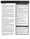
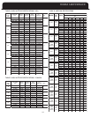
TABLE 1A
FURNACE TEMPERATURE RISE
Fur nac e Mod
Model
el Tem per atu re
Rise
35 – 65 F
30 – 60 F
35 – 65 F
30 – 60 F
35 – 65 F
30 – 60 F
30 – 65 F
TAB
LE 1B
TYPICAL AIR FLOW
CF M Re qu ired for a T of:
35 45
55 65
35-2
50-3
70-3
70-4
85-3
85-4
100-3
100-4
100-5
115-5
35-2
50-3
70-3
70-4
85-3
85-4
100-4
100-5
115-5
737 574 469 397
1053 819 670 567
1433 1114 912 771
1433 1114 912 771
1791 1393 1140 964
1791 1393 1140 964
2107 1639 1341 1134
100-3
2107 1639 1341 1134
2107 1639 1341 1134
2423 1884 1542 1305
135-5
135-5
2844 2212 1810 1532
T
he equal friction chart, as published by ASHRAE and HRAI,
is the basis for the various air duct calculators available
through heating supply companies.
NOTE: The return air system is equally as important as the
supply air system. An undersized return air system will
prevent sufficient quantities of air from reaching the supply
a
ir system, properly sized or otherwise, and will
consequently reduce the service life of the furnace and its
components.
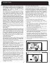
LOCATION of UNIT
GENERAL:
1. The furnace is not weatherized. Select a dry indoor
location.
2. Select a location where the furnace venting can be
routed between the furnace and the chimney or B-Vent
with a minimum of lengths and fittings. Be sure to
check that the proposed routing will meet code
requirements with respect to minimum clearances.
3. Select a location as near as possible to the existing or
proposed duct system.
4. The furnace location must permit access for servicing,
and be within the clearance to combustibles guidelines
as marked on the appliance rating plate.
5. The furnace should be installed on a firm base when
installed in the upflow position. This is typically a
concrete floor if installing the furnace in a basement.
6. If the furnace is being installed so that the return air
will enter through the bottom, the perimeter of the
furnace must be properly supported.
7. When installed in the horizontal position, the furnace
may be supported from the bottom, or suspended.
8. When installed in the down flow position on a
combustible floor, subbase kit #30476 is required
(contact manufacturer for availability).
OTHER CONSIDERATIONS:
• This furnace is not to be used for temporary heating of
buildings or structures under construction.
• If this furnace is to be used with air conditioning and is
to be installed in an area over a finished ceiling or
living area, install a field fabricated auxiliary drain pan
under the furnace to protect that area from accidental
condensate spills. The auxiliary pan should be large
enough to collect accidentally spilled condensate from
the air conditioning evaporator coil assembly if
applicable. Follow local codes.
•
These furnaces are approved for installation in attics,
alcoves, utility rooms, closets and crawlspaces. If this
furnace is to be installed in a utility room, be sure that
it is located in such a way as to allow access for
servicing or the removal of any other appliance, (hot
water heater, for example).
•
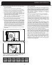
If the furnace is to be installed in a garage, the burners
must be a minimum of 18 inches (460 mm) above the
floor.
•
If the furnace is to be installed in a commercial (repair)
garage, the burners must be a minimum of 4.5 feet
(1375 mm) above the floor.
•
The furnace must be protected from physical damage
by metal barriers or other acceptable means.
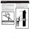
Existing ductwork should be assessed for its air handling
capabilities. For residential applications, the recommended
air velocity of a supply air trunk duct is 700 feet per minute
(fpm), and should not exceed 900 fpm. The recommended
air velocity of a supply air branch run is 600 fpm, and should
not exceed 900 fpm. These values are slightly lower for
flexible ducting. The recommended air velocity of a return
air trunk duct is 600 fpm, and should not exceed 700 fpm.
The recommended and maximum air velocity of a return air
branch is 600 fpm.


