10
WARM AIR FURNACE
V
ENT CONNECTOR
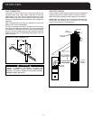
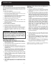
The furnace may be vented with a listed single wall or
T
ype B double wall vent connector to a B-Vent or lined
masonry chimney. Most United States jurisdictions require a
minimum 28-gauge galvanized single wall vent connector.
Most Canadian jurisdictions require the vent connector to
have corrosion resistance equivalent to 24-gauge
g
alvanized sheet metal.
Observe the rules concerning clearance to combustibles.
T
he vent connector must be readily accessible for
inspection, cleaning or replacement.
Keep the vent connector as short as possible by locating the
f
urnace as close as practical to the vent or chimney. Avoid
unnecessary turns or bends that create resistance to the
flow of the vent gases. Fittings such as elbows add
resistance to the vent connector.
Use Type B vent connectors in attics, crawl spaces, or other
cold areas. Install thimbles that meet clearance to
combustibles requirements and local code requirements if
the vent connector must pass through a wall or partition
constructed of combustible material. The preferred method
to join vent connectors to a vent or chimney is by individual
connections. If two vent connectors must be joined before
the vent or chimney, use a correctly sized wye or tee-wye
fitting as close to the vent or chimney as practical.
All furnace collars are 4 inch. When the United States ANSI
Z223.1 / NFPA 54 or Canadian B149 venting tables specify
the use of 3 inch venting, use a 4 to 3 reducer at the furnace
collar. When the venting tables specify the use of 5inch
venting, use a 5 to 4 reducer at the furnace collar.
Secure all single wall vent connector segments together
with a minimum of three sheet metal screws per joint.
Secure the vent connector to the furnace collar with a
minimum of three sheet metal screws. Type B vent
connectors do not require sheet metal screws since they
have their own locking system.
I
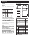
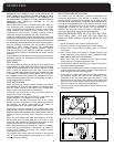
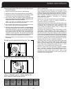
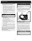
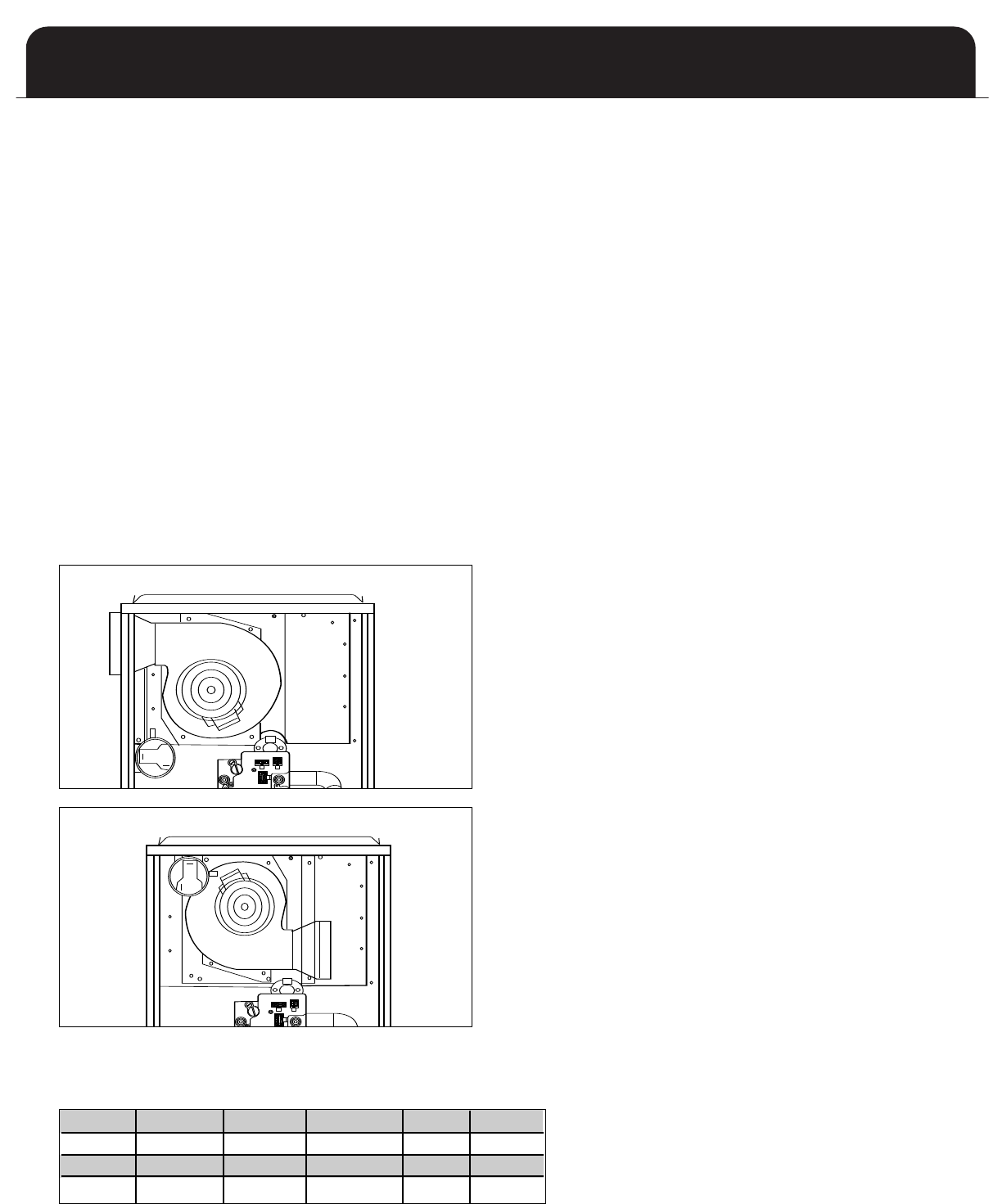
NDUCER ROTATION STEPS ON 35-2, 50-3 (See Figures
5A and 5B below)
1
. Ensure all power to the furnace is disconnected.
2. Disconnect inducer wiring and pressure switch tubing.
3
. Remove four screws securing inducer and inducer plate
to flue box cover plate. (see figure 4A on page 9)
4. Place inducer plate and gasket in desired position and
locate mounting holes required. NOTE: INDUCER PLATE
A
ND GASKET MUST BOTH BE ROTATED.
NOTE: Any holes not concealed by the inducer gasket
require the use of screws to plug the holes.
5. Secure inducer and inducer plate to flue box cover using
four screws in the correct mounting position.
6. Carefully remove side panel knockout corresponding to
the venting application and install cover (part #30763)
underneath top panel using two screws (field supplied).
In the event of a right hand discharge inucer application,
the pressure switch will have to be relocated to the
underside of the top panel. The pressure switch tubing
will have to be cut to the length listed in Table 4 (below)
if inducer is mounted in right hand configuration.
7. Reconnect inducer wiring and pressure switch tubing to
the inducer
OFF
ON
C2
C3
C1
OFF
ON
C2
C3
C1
OFF
ON
C2
C3
C1
OFF
ON
C2
C3
C1
OFF
ON
C2
C3
C1
OFF
ON
C2
C3
C1
OFF
ON
C2
C3
C1
OFF
ON
C2
C3
C1
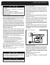
FIGURE 5A: LEFT INDUCER POSITION (35-2, 50-3)
FIGURE 5B: RIGHT INDUCER POSITION (35-2, 50-3)
TABLE 4: PRESSURE SWITCH TUBING LENGTH FOR
RIGHT INDUCER POSITION (IN INCHES)
35-2
50-3
70-3
70-4
85-3
85-4
12 1/2” 12 1/2” 13 1/2” 13 1/2” 13 1/2” 13 1/2”
100-3
100-4
100-5
115-5 135-5
13 1/2” 13 1/2” 13 1/2” 13 1/2” 13 1/2”


