


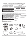

licensed electrician.
Remote Transmitter
Unit Detail
1 2 3 4
ON ESE
8
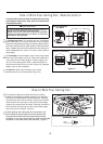
How to Wire Your Ceiling Fan - Remote Control
If you feel that you do not have enough electrical wiring
knowledge or experience, have your fan installed by a
ʆ
WARNING
To avoid possible electrical shock, be sure electricity is
turned off at the main fuse box before wiring.
NOTE: If you are not sure if the outlet box is grounded,
contact a licensed electrician for advice, as it must be
grounded for safe operation.
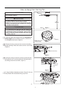
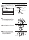
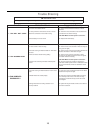
1. Setting the Code: The remote unit has 16 different
code combinations. It may be necessary to test a couple
frequency code settings to improve signal reception and/or
eliminate interference from other remote control household
items. Multiple fans should have different code settings to
allow independent fan control. To set the code, perform
these steps.
2. Transmitter: remove battery cover. Press firmly below
arrow and slide battery cover off. Slide code switches to
your choice of up or down position. Factory setting is all
up. Do not use this position. With a small screwdriver or
ball point pen slide firmly up or down (Figure 1a). Replace
battery cover on the transmitter.
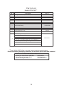
3. Receiver: Slide code switches to the same
positions as set on your transmitter (Figure 1b).
Receiver Unit Detail
Figure 1b
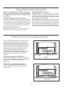
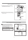
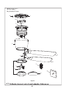
How to Wire Your Ceiling Fan
1. Connect the green grounding lead from the ceiling
bracket to the supply grounding conductor (this may be a
bare wire or wire with green colored insulation). Securely
connect wires with a wire connector. Securely connect the
white receiver wire (coming from fan) to the white supply
(neutral) wire using a wire connector. Securely connect the
black receiver wire (coming from fan) to the black supply
wire using a wire connector. (Figure 1)
x 3WIRE
CONNECTORS
HARDWARE USED:
Figure 1
Figure 1a
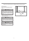
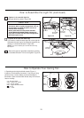
2.
After splicing and making the wire connections, the
wires should be spread apart and turned upward with
the grounded conductor and the equipment-grounding
conductor on one side of the outlet box and the ungrounded
conductor on the other side of the outlet box. (Figure 1)