


UK/IRL
27
UK/IRLUK/IRL
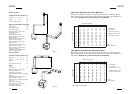
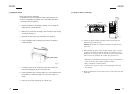
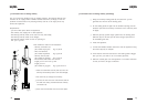
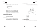
5. INSTALLATION OF THE FLUE
5.1 Connections with use of concentric duct material
- Build the system starting from the appliance on.
- Make a hole of ø 153 mm for the wall or roof mounted terminal.
- Make sure you place the pipes in the right direction, the narrow
end towards the appliance.
- Make sure the pipes are fixed sufficiently, a wall clamp every 2m, so
the weight of the pipes is not resting onto the appliance.
- The outside of the pipe can become hot (140 degrees). Stay 50 mm
away from wall surface or sealing. Make sure to provide sufficiently
heat resistant isolation when going through the wall or roof.
- Because of expansion or cooling down the concentric pipes can turn
loose. It is recommended to fix the spring clip with a self tapping
screw at inaccessible places.
- To get the exact measure flue length you can use cut down-
concentric pipe, wall mounted terminal or roof mounted terminal. To
obtain a smoke sealed connection, the inner pipe must be 20 mm
longer then the outside pipe.
- The horizontal pipes need to rise away from the appliance at a rate
of 3 degrees per metre.
UK/IRL
26
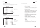
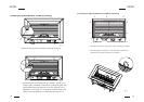
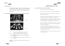
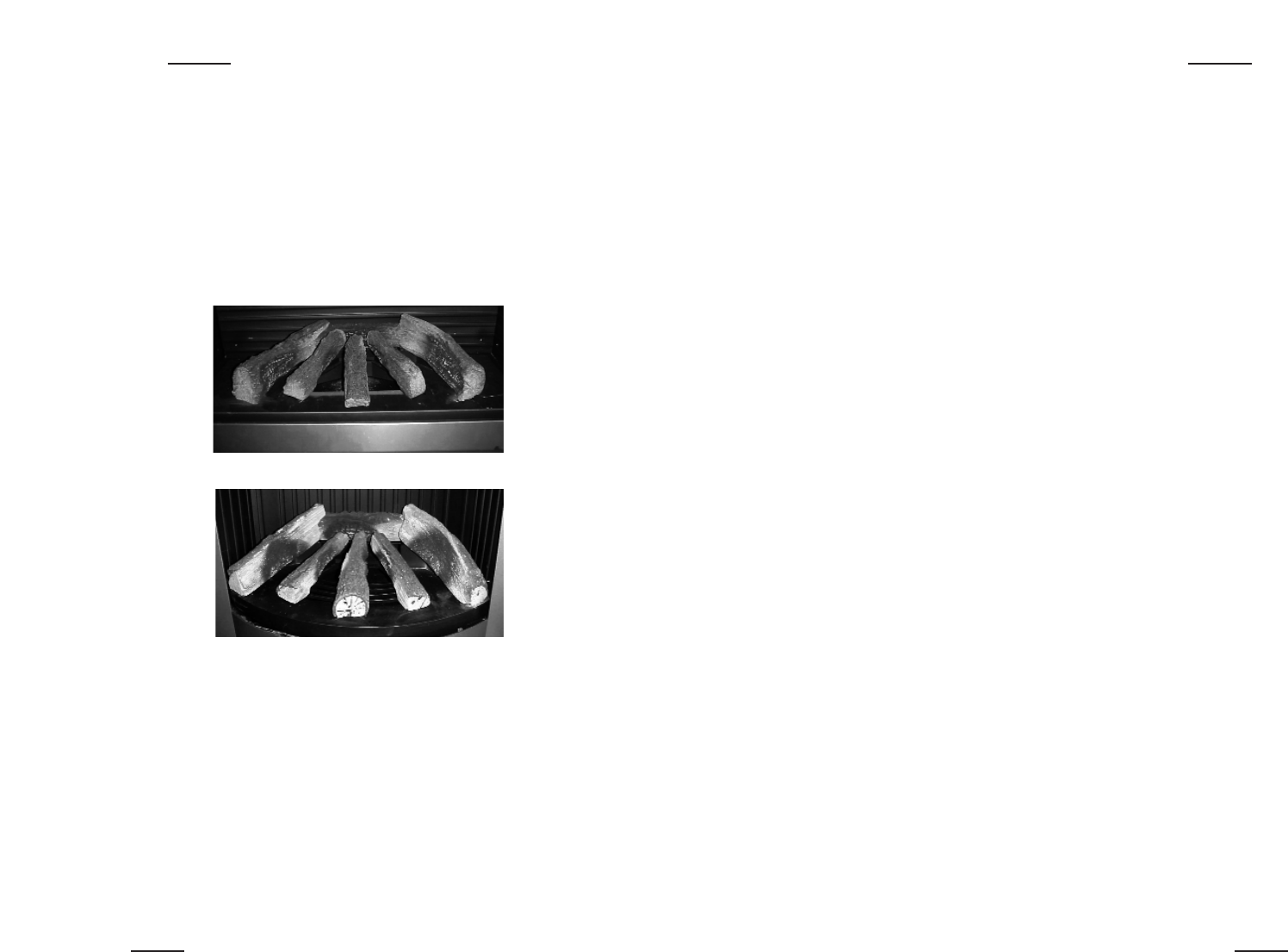
4.6 Placing the log set
Never place extra elements of any kind into the combustion chamber.
To guarantee good combustion, the log set may only be installed in
the way specified by Faber International. Any other arrangement can
lead to soot on logs or window. Do not use the fire with broken or
missing logs.
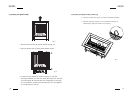
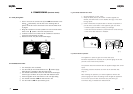
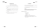
4.6.1 Placing the log set Widescreen, Whisper, Spectra Nova, Misty and Cadra Nova
On the bottom of the logs is a identification:
• L location on the left side resting on the rear log.
• R location on the right side resting on the rear log.
• 1 dimple first log left placed over the burner and resting on the
burner tray.
• 2 dimples placed in the middle over he burner and resting on the
burner tray.
• 3 dimples the right side log placed over the burner and resting on the
burner tray.
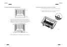
Attention! Beware that there are no embers between the logs and the
burner tray.
fig. 18
fig. 19