


8
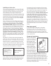
Remember: Apply glue only to the outside of the tubing.
Hint: When upstairs, remember to aim the elbow
downward. Other ways to reach the upstairs in your
home are through the interiors of closets or pantries,
beneath a staircase, or with fl oor inlets. If the inlet
valve will be serviced from the attic, shorter pieces of
tubing joined by couplings may be required because of
overhead space restrictions. Again, measure and test
fi t. When gluing, work quickly to prevent the glue from
drying before the tubing reaches the inlet valve.
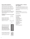
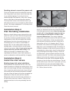
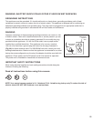
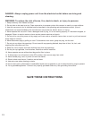
Installing an automatic sweep inlet.
If you’re installing an automatic sweep inlet...an
automatic dustpan...a very popular option for the
kitchen, mudroom, and bath...here are some pointers.
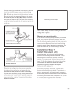
First, determine the best place to install the sweep
inlet...usually beneath a cabinet...and remove any
molding or baseboard. Drill a pilot
hole using a length of wire coat
hanger and fi nd the wire in the
ceiling below. Drill up through the
fl oor beneath the cabinet to check
for obstructions...and to make sure
you can connect the tubing to the main line. If there
are no obstructions, enlarge the hole in the fl oor
beneath the cabinet and check the clearances.
Now, return to the kitchen/mudroom/bath to measure
and saw the rectangular hole for the sweep inlet and
fasten the inlet into place. In the basement, attach
the tubing and string the low-voltage wire just as you
would for any inlet. Hint: See sweep inlet manual for
details.
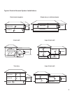
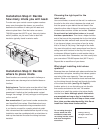
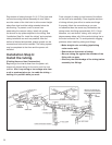
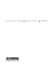
New Construction inlet valve installation.
Select a site for the inlet valve and drill a pilot hole
through the fl oor. Go below to check that the tubing
path is clear of present, or future, obstructions such as
fl oor joists, heating ducts, plumbing, wires, etc. At the
inlet valve location, drill a 2-1/4" (5.7cm) diameter hole
through the sole plate. The hole should be 2" (5.1cm)
from the side of the stud and centered between the
front and back edges of the sole plate (Fig. 05).
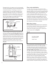
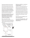
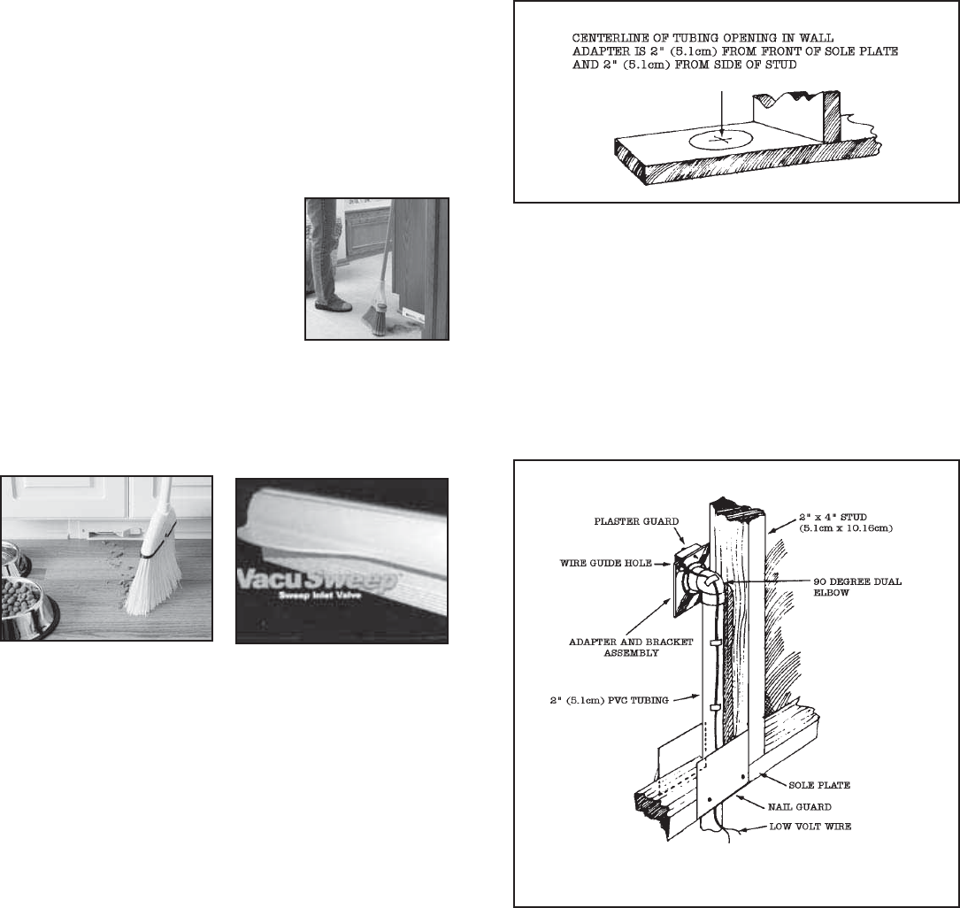
Glue a length of tubing into a stud-mounting bracket
assembly. Cut a length of low-voltage wiring, bring
approximately 6" (15.24cm) through top wire guide
hole in stud bracket assembly and double it back into
elbow hole. Tape wire to tubing at assembly elbow
and again close to end, and tuck remaining wire into
bottom of tubing. Screw plaster guard onto face of
assembly (Fig. 06).
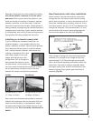
Cut hole 6-3/4" x 1-3/4"
(17.15cm x 4.45cm)
Cut hole 6-5/8" x 2-3/8"
(16.83cm x 6.04cm )
VacPan VacuSweep
Fig. 06
Fig. 05
Stud-Mounting Bracket Assembly (New Construction)