


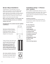
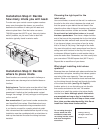
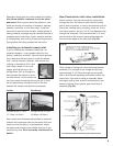
Deciding where to mount the power unit.
To be sure that dust and dirt are effectively removed
from living areas in your home, mount the power unit
in your attached garage. If you do not have an
attached garage, the basement, utility room, storage
room or mud room is the best alternative location.
Find a spot that is close to an electrical source, yet
with plenty of room for air to circulate on either side of
the unit. You’ll need a dedicated 15- or 20-amp circuit.
Check the owner’s manual.
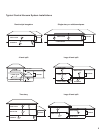
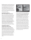
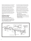
Installation Step 4:
Plan the tubing installation.
Before you install tubing to carry dust and dirt to the
power unit, plan your route. Run the tubing beneath
the sub-fl oor whenever possible because it makes
tubing easier to work with and creates the shortest
path between the inlet valves and the power unit.
If the tubing has to run next to a water heater or
chimney fl ue—for your safety and to comply with
building codes—use metal central vacuum system
tubing for that section. Hint: A local central vacuum
system dealer may provide metal tubing. If the
tubing runs through an unheated attic or other
unprotected environment, wrap it with insulation to
prevent condensation and the possibility of clogging.
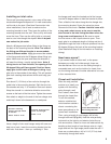
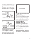
Installation Step 5:
Install the inlet valves.
Existing home inlet valve installation.
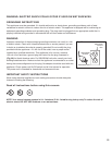
Directly beneath the proposed inlet site, use a fl at-
bladed screwdriver to wedge the molding aside. Then,
take a wire coat hanger and snip a long straight piece
from it. Insert the wire into the chuck of your drill and
then holding the drill vertically beneath the intended
inlet site, slowly drill down into the fl oor alongside the
baseboard or where the wall and fl oor intersect.
Release the wire from the drill chuck and leave it in
the pilot hole to serve as a locator. Then go to the
basement and look for the wire protruding from the
ceiling.
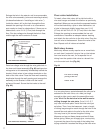
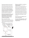
Now you can see where the inlet valve is going to be
above you. Measure from the wire to fi nd the center
of the sole plate and wall cavity. Note: You may want
to drill a 3/4" (1.9cm) diameter inspection hole to
avoid cutting into the bottom of a stud or other
inner-wall obstructions. Then using a fl ashlight
and/or probe, inspect the interior of the wall to be sure
there are no obstructions. If there are obstructions,
you may have to move the inlet site. If there are no
obstructions, drill a 2-1/4" diameter hole (5.7cm) in
the bottom of the hollow wall through the sole plate.
Make sure to cut in between the walls. The tubing is 2"
(5.08cm) in diameter, so the hole will give you room to
manipulate the tubing. Again, check for obstructions
using a fl ashlight and a length of tubing. If there are
no obstructions, go back upstairs and mark the inlet
location on the wall. To do that, at the electrical outlet
adjacent to the inlet site, measure up from the fl oor
to the center of the outlet. At the proposed inlet site
measure up from the fl oor the same distance. This will
be the center of your inlet valve. If you prefer, you may
locate the inlet at a more convenient height. Some
homeowners prefer the inlet at fi ngertip height, about
30" (76.2cm) above the fl oor.
5